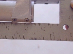
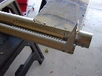
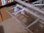
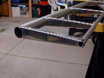
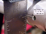
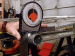
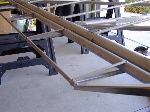
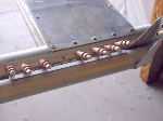
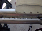
Both the clip wing and long wing with fiberglass tips will come from QC with the aileron unfinished at the outer end. Measuring and finishing the outer end of both Ailerons will be required. Further, the fiberglass tips are only available for the CII plane right now. If you order a CI kit it will come with standard factory bow tips, fabric covered, for either clip wing or long wing, and finished ailerons.
Ernie will be installing the four (4) hinges per Aileron as specified by the factory.
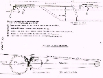 Click to Enlarge |
The drawing to the LEFT is from the Challenger Builders Manual, page #13. This shows the factory recommendation for mounting the aileron hinges. |
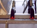
Prop up the rear edge of the aileron with a wedge and check the surface alignment with a straightedge placed on the wing ribs at various locations. Adjust the aileron position at the clamped hinges until the straight edge coming down off the wing shows the aileron top surface to be almost level with it. Then mark the aileron hinges on the the aileron torque tube for drilling.
SPECIAL NOTE: When drilling for the rivets, make sure you arrange the rivets on each side of the hinge so that they don't hit each other when the hinge is folded upward. There is not all that much travel available on those hinges to start with, and if you put the rivets directly opposite each other, the rivet heads on one side of the hinge will hit the rivet heads on the other side of the hinge, which will result in less hinge travel.
The instructions mention this, but it needs to be emphasized. Making an error with those hinge rivets is not correctable after the holes are drilled in the spar and aileron tube. All you can do then is "dope slap" yourself for not paying attention.
NOTE: The inboard hinge next to the aileron horn gets 8 rivets per side, for a total of 16 per hinge. The 3 outboard hinges only get 4 rivets per side, total of 8 per hinge.
Once you have finished drilling all the remaining rivet holes in all four (4) hinges, mark each hinge with an identifying letter or number you will remember later when you eventually rivet the hinges on permanently. Now, remove all the temporary rivets and put your hinges away till they are needed later.
Repeat this process for the other wing.
That's it; you are finished setting the hinges for the ailerons.
NOTE: For the removal of rivets, see our web page on, Removing a Rivet. Also available at the bottom of our "FEATURED BUILD PROJECT" drop down menu.
When you put the aileron back in position for final mounting, after covering, you will use short stainless steel rivets on the aileron tube, and long stainless steel rivets on the wing spar side.
We will now move onto "Fuel Tank Holder & Placement in Fuselage".
Please return to the Featured Build Menu by clicking on your browser's "BACK BUTTON".
