Build Your Own Comm Antenna
By: Jim Hayward


Anyone who has ever priced commercially made comm antennas for aircraft knows how spendy they can be. This article will show you how to make your own for a fractional cost of a commercial antenna. It will work as well since it's a quarter-wave design just like most of the commercial ones. Most aviation comm antennas are vertically polarized which means everyone's communications system works best if the antennas are mounted with the active or radiating element of the antenna mounted vertically. TV antenna systems are horizontally polarized while FM systems are both vertical and horizontal (to catch both the mobile and home listeners).


Locating Parts

Click to Enlarge
         

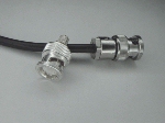
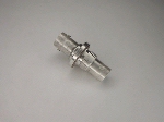
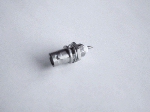
A good source for parts is a local two-way radio shop. Radio Shack or an electronics supply house may have the parts as well but the two-way shop is a really good bet. You'll need the following items: an antenna rod (may be called a replacement whip or antenna whip) at least 25" long (ask for one for a high-band radio), a male BNC connector (push on and twist-to-lock), a chassis mount BNC connector (female mate which may also be called a bulkhead connector) or a bulkhead adapter which has the female end on both ends for connection of a cable instead of soldering, an L-bracket (optional), a bench grinder, and a micrometer. Common hand tools such as wrenches, pliers, and files will come in handy as well. The antenna assembly which you make, will simply connect onto the BNC mating connector mounted somewhere on the plane. You'll also need coax cable such as RG58A and two male BNC connectors for the cable.

         
Click to Enlarge


Click to Enlarge


Fabricating the Antenna Element

Let's start with the antenna element (rod) itself. Most any two-way radio shop will have some of these around. It's stainless steel and a good scrounger may even find an old CB roof/trunk mount whip laying around somewhere that can be utilized. Two-way shops will have new BNC connectors and (probably) used ones as well which may be obtained for free. The used ones probably won't have a center pin but you won't need one anyway if you grind your own to be part of the rod as shown below. Try to find a BNC connector that's meant to be field repairable instead of a crimp-on type. The crimp-on kind will be adequate but have a much narrower neck for the rod to fit thru which may make it more difficult when epoxying the assembly. Even old/bad video cables from a TV studio will have usable BNC body shells on them. Just discard the cable and center pin (which will not be usable anyhow).

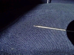
The rod needs to be cut down such that approximately 23-1/2" (or whatever length you have calculated for your operating requirements) will be sticking out of the BNC connector. You'll need to allow an additional 1/2 to 3/4 inch for the BNC body. Measure from the tip (end with the ball) and use a file to notch the element at approximately 24" to maybe 24-1/4" depending on your BNC connector's "length". You can file completely thru the rod or most of the way. Then with some pliers, bend it back and forth so it will break off. A bench grinder may also be used to cut it off at say, 25 inches then grind it on down to your required length. Now, file the end smooth and you're ready to shape the "center pin". This 23-1/2" is not super critical but is a good starting measurement. You can decide on your own length depending on the frequency range or channel spread (lowest and highest frequency you'll be using) and where you'd like your "center" frequency to be. See Appendix A at the end of this article for more information.


Click to Enlarge


Click to Enlarge
         

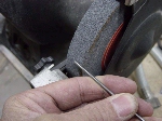
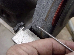
The center pin's diameter on a 50 ohm BNC connector is .050" and it's length is approximately 5/32". Using a bench grinder and micrometer, one can nicely grind down the end of the element's diameter so there's a small "pin" on the end of the rod. This will make the center pin integral with the element. This way you don't have to try and solder stainless steel to the BNC's brass center pin.

If you're unsure how easy or hard it might be to fabricate the pin, you can practice grinding on the scrap piece that was cut off of the rod . A relatively easy method is to rotate the piece in your fingers as the end is held gently against the grinding wheel. You may use a coarse wheel to start but as you get close to the correct diameter, you should switch to a fine wheel. You'll need to try and keep the pin's edges straight and not tapered from the tip to the thicker part of the rod. Your micrometer can help with this as you measure along the "pin" for as straight a pin as you can get.

         
Click to Enlarge

Don't go less than the .050" but try to get there or maybe at least to .052". If you go below .050", the center pin can't make reliable contact with the mating connection and you have a real possibility of damaging your radio due to an unacceptably high reflected power from an open connection. This would be the result of the antenna not contacting the mating center pin and would be like transmitting without the antenna connected. Go thicker than that and while the female connector will make contact, the larger diameter can spread that connector's 4 contact fingers beyond what they're designed for. If you don't have a micrometer, get one.... it can be had for less than $20 at discount stores comes in handy anyway.

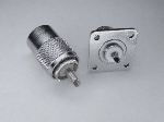
On another note, some of you may find an old 8' CB whip. That's a quarter-wave whip for CB frequencies. It could be cut down and used but wouldn't fit in the BNC. However, a PL259 will probably work. That's the large CB connector with the screw-on sleeve. You won't need to make that center pin and will still have to solder the whip into the connector but it should work. The mating connector for it will be an SO239. Both should be available at Radio Shack. You'll need to drill a round hole for the SO239 to fit into and there'll also be four 4-40 size holes drilled for the screws to attach the connector to the L-bracket. "These connectors may also be listed as a "UHF Connector".

         
Click to Enlarge


Antenna Assembly

Once your micrometer shows the correct diameter, insert the element into the male BNC connector for a trial fit. The center pin should extend just to the edge of the inner part of the BNC connector. You can check this by standing the assembly up and pushing the rod all the way down into the BNC body. You may or may not have to dress down the rod just above the pin area so it fits down thru the BNC's white teflon "washer" inside the body. Once a snug fit is obtained, the rod may be epoxied into the BNC connector. You may need to place a very narrow strip of electrical tape or something around the rod above the pin if it's is a loose fit in the white teflon "washer". You don't need epoxy leaking down thru the connector and into the pin area. The tape will block it from leaking out around the rod.

The 5 minute variety of epoxy will work well since you won't have to hold things in place very long before the epoxy sets up.... just be sure you have everything ready to go. Insert the rod part way into the connector inserting it from the BNC's "back side" so the pin is engaged in the hole of the white teflon "washer". If you have the narrow-necked BNC, drip some epoxy onto the rod and into the connector back then slowly rotate and push the rod on thru the connector as you add epoxy. Rotation insures that the epoxy gets coated in the BNC's neck. If you have the wide necked BNC you can just insert the rod and, while standing the assembly on end, drip the epoxy around the rod and into the open back of the connector. Keep the rod centered in the BNC connector while you let the epoxy set up and.... wala! You're antenna is now finished and it didn't cost anywhere near as much as a commercial one!


The Antenna Mount

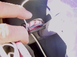
Now that the antenna itself is finished, you'll need a mount of some sort for it. The chassis mount is one that has the female mating connection for the antenna assembly on one end with the other end of this connector having a solderable center pin for your coax cable from the radio. You may get a ring terminal for the shield to solder to if the connector doesn't come with one.


Click to Enlarge
         

The chassis mount will be threaded in the middle and include a thin nut along with a star lockwasher. The ring terminal will go under this nut and lockwasher and next to the L-bracket or root tube. There will also probably be a flat "side" to the connector's threaded portion. The mounting hole should be shaped the same way as this prevents the connector from turning in the hole when the nut is tightened up. Use a smaller size drill for the hole then start filing to enlarge the hole for the correct shape. This is a little more difficult than just drilling a hole but is easier for final assembly.

         
Click to Enlarge


Click to Enlarge
         

If you don't want to solder anything, you can get a BNC bulkhead adapter which, as mentioned before, has a female mating connector on each end. With this connector, you simply need to drill a properly shaped hole in the top of the root tube or in your L-bracket (to be mounted where ever) then mount the connector, snugging up the thin nut. The antenna assembly will then be mounted on one end with the coax cable from your radio (and a BNC connector on each end of said cable) on the other end. You may purchase BNC connectors at any good electronics supply store.

         
Click to Enlarge


Matching the Antenna to the Radio

The length of the coax cable may be of some concern if your radio's 50 ohm output impedance doesn't match your antenna's input impedance. This mismatch shows up as VSWR or voltage standing wave ratio. The CB'ers and hams simply call it SWR and measure it with an SWR meter. Ideally, a 1:1 match is desired, however, this is usually next to impossible to achieve even in the broadcast industry.

Ham's typically run 1.5:1 to 2:1 with some antenna systems even giving 2.5:1 or 3:1 without a substantial loss of signal. The typical rubber ducky antenna falls into this category and still works okay in most cases. So basically, we want to utilize half-wave lengths (or multiples of that) which are approximately 31", 62", 93", 124", etc. (based on using a center frequency of 121 MHz and 66% velocity factor).

The better the match one can achieve between the antenna and the radio, the less power and voltage that's reflected back into the radio's output stage due to the mismatch. This generally is of little concern until the mismatch gets up beyond say 3:1 or so. The damage can consist of simply shorting out the final output transistor or be as complex as the final output transistor and burning up some associated components. Don't ask me how I know. :-)


Mounting Locations

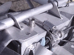
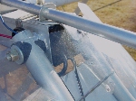
There have been several mounting locations utilized for our Challengers. The root tube up near the front and in the middle, the wing strut attach bracket, and the fuselage belly are some we are aware of. Using the bottom of the aircraft will necessitate bending the antenna element so it won't drag on the ground when taxiing. A ground plane and fabric reinforcement will also need to be fabricated for use in that location. The sheet metal at the root end of the wing is a good location to mount your antenna although some reinforcment of the mounting area may be needed. The root tube along with the down tubes will also provide a good ground plane. The wing spar and strut juncture will be okay as well since the spar, strut, and ribs become the ground plane. While the signal may be a little directional due to the ground plane not being completely "around" the antenna rod, it will work fine.

If using the forward root tube location, the coax cable may be routed from your radio location, up thru the forward down tubes and to the antenna. The middle down tubes could be utilized if it's desired to mount the antenna on an L-bracket riveted to the middle of the root tube on one side. For the wing spar and strut juncture, your coax cable can be routed along the strut and inside the streamline covers. Several locations are available for satisfactory to great performance so you'll have to be the judge of what you want for your particular aircraft. For example, with the coax cable and copper tape antennas mentioned in Appendix B, an antenna can be mounted in the fiberglass nose of the aircraft with good performance. Those same antennas could lay secured in the bottom of the fuselage as well. There are many possibilities here.


Happy Communicating!

Once you have the parts in hand, building the antenna and mount can be accomplished in a couple of hours or so. You'll have a transmission range on the order of 30 to 70 miles depending on your particular radio's output power. Reception routinely should be 50 to 70 miles depending on your radio's receive sensitivity as well as the other station's transmitter/antenna setup.

Now, should you decide not to make your own antenna, there are ready-made antennas that can be purchased and mounted using the same mounting methods as stated above. We provide links to some of those products in Appendix B. One can also do a "Google search" on the web. Search for "aircraft antennas" and you'll find plenty to choose from.


APPENDIX    A

The Antenna

A quarter-wave antenna is theoretically 36 ohms since it's half of a dipole antenna which is 72 ohms. The dipole antenna needs no ground plane but can you imagine a 46" antenna sticking up somewhere on the outside of our plane??? About the only place I could see doing that would be a half-wave dipole attached vertically to the wing spar/strut juncture.... weird!

On a dipole, the shield of the coax feeds one half of the antenna while the center wire of the coax feeds the other half. In a quarter-wave antenna installation, the coax's center wire feeds the insulated antenna element while the shield "feeds" the ground or is grounded to the metal structure. The metal material (aircraft structure) around the antenna becomes the other half of the antenna system.

The formula for figuring a half wavelength is: 492 / freq(in MHz) x 12 to give the length in inches. Therefore, to figure a quarter wavelength, the formula would be: 246 / freq(MHz) x 12. However, those figures are generally for frequencies below 30 MHz or so (shortwave bands). It's been found that as your frequency increases above 30 MHz or so, the ends of the antenna begin to affect the real world length and calculations need a reduction of about 5%. So we use a slightly different formula: 236/freq (MHz) for antenna lengths at our operating frequencies.

Example: find a quarter-wave antenna length for a 121 MHz operating frequency.

    (236/121x12) 236 / 121 = 1.95' x 12" = 23.4" for the rod.
The ground plane radials would be 5% more or about 24.6". If they are longer, it's not a problem.

If, for example, you use 118.0 MHz for the lower end of your "operating range of channels" and 126 MHz for the upper end, you'll find that the center frequency will be 122 MHz. Therefore if you cut your antenna for 122 MHz it will be the most efficient at that frequency with a (very) slight loss at 118 and 126. This loss will probably only be measurable with fancy test equipment. The engths for those two frequencies will be approximately 23.8" for 118 MHz and approximately 22.3" for 126 MHz. So we have a difference of 1.5" over that 8 MHz channel spread. This is why we say the length is nothing to get really anal about. In our 121 MHz example, a half inch either way from the 23.4" calculation will work just fine. Of course, there comes a point where the SWR *is* a problem but, for our purposes, we can ignore it since the "window of operation" naturally limits the problem for us.

The ground plane, or counterpoise as it's properly called, sits at the base or feedpoint (where the coax is connected) of the antenna. Ideally, the ground plane would be a disc with a radius 5% or more than the active (vertical) element or, in our example of 23", about 24-1/4". However, on our aircraft, this is not practical. We can use 4 wires or rods in place of the disc with excellent results but again, depending on the aircraft/application, it may not be practical. We can, however, get quite acceptable results by using the existing root and down tubes as a ground plane. Mounting the antenna out on the wing strut attach bracket will utilize the wing spar and strut, also with good results. An L-shaped bracket can used for the antenna mount on both the wing spar/strut location and works equally well for the root tube if you have no desire to drill a hole in that tube.


The Antenna/Coax/Radio Match

Not getting too technical, a coax cable has what's called a "velocity factor". Depending on the materials the cable manufacturer used, this velocity factor can range from about 66% to around 85%. Most of what we can buy is of the 66% variety. What this means is that the radio signal only travels 66% of the distance in the cable that it would out on the antenna rod itself given the same amount of time or, to think of it another way, it travels only 66 to 85 percent as fast.

Radio waves radiate from the antenna much the same way that a pebble thrown into calm water causes ripples to propagate from the entry point. There are peaks and valleys to these ripples (relative to the calm water) the same as there are plus and minus voltage levels (relative to a zero voltage) in a transmitted signal. If you go peak to peak (plus to plus) or valley to valley (minus to minus), you've traveled 360 degrees or one wavelength. Travel peak to valley (plus to minus) or valley to peak (minus to plus) and you've gone 180 degrees or a half wavelength. A travel of 90 degrees is a quarter wavelength (plus to zero, zero to minus, etc). So a 121 MHz signal will have 121 million peaks in one second.

A quarter wavelength (or multiple thereof) of coax cable can act as an impedance transformer and is used widely to match systems if needed. Conversely, a half wavelength (or multiple thereof) will see the same impedance at each end of the cable. Utilizing a half wavelength (or lengths) of coax allows us to get the best match possible without reverting to matching sections of coax which adds some complexity. Granted, the differences may not be so much as to be noticeable but they *can be* as well, if the mismatch is large enough.

The mismatch between a 50 ohm radio output and a 36 ohm quarter-wave antenna is approximately 1.5:1 which is the best we can hope for with a perfect ground plane. If you were using the 4 radials, as many base station CB antennas do, and started drooping those radials downward towards the ground, the impedance would start rising towards 72 ohms since the antenna would start looking like a dipole. At some point the impedance would be 50 ohms and the same impedance as the radio's output. If you had this scenario, the length of the 50 ohm coax cable would not matter at all since the radio, coax, and antenna are all a perfectly matched 50 ohm impedance. The mounting location can also affect the input impedance of the antenna.

Since a perfect match will not happen on our aircraft, and we don't want to transform any impedances for a worse mismatch, we try to utilize half wavelengths of coax cable (or multiples thereof) to connect our antennas to our radios. To obtain the coax cable length for a given frequency, you first have to calculate what your half wavelength will be (NOT the quarter wavelength the antenna uses) based on the next paragraph. Then multiply that times the cable's velocity factor.

Example: find the half wavelength for RG58A (50 ohm coax cable, 66% VF) at a 121 MHz operating frequency.

    You already know that a quarter wavelength is 23.4" from the previous antenna element example. Now mulitply that by 2 for a half wavelength which is what we want for the cable. Then multiply that answer by the velocity factor of 66% (or .66) in our example coax. 23.4 x 2 = 46.8     46.8 x .66 = 30.88 or just over 30-7/8" which is close enough to call 31".

Remember, we don't need to be really anal about all this. If your radio is more than 31" from the antenna, simply use the next multiple which would be about 62" and so on.


APPENDIX    B

Pre-Made Antennas - Retail

Some commercially made antennas are available from the following places with a short description of their antenna product(s). The alphabetical listing in no way denotes one antenna better than another.

Aircraft Spruce & Specialty They market a whole slew of antennas for your particular needs.

Miracle Antenna They market a half wavelength antenna made of coax cable that can fit into the fiberglass nosecone of your aircraft.

RST Engineering They have an antenna kit available to make up to 6 antennas utilizing copper sticky tape and toroid ferrite rings to fine tune the system.

Wicks Aircraft Supply They market a half wavelength antenna which is glued to the fabric or fiberglass for mounting. They also have copper foil tape to make your own if you want to go that way.