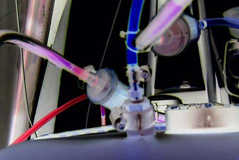
If you are building a Challenger and have never designed or worked with a fuel system before, the prospect can be a little intimidating, if not downright scary! After all, a casual glance at most fuel systems on ultralights reveals a maze of fuel lines and tubes seemingly going everywhere.
This article is intended to show you what's required of the fuel system, what optional features may be added, and how to put it all together after you decide exactly what you want your system to include.
We don't go so far as to make a recommendation of a particular system. After all, there is no universal agreement on how it should be done. There is no single "best method," nor is there a "standard" way to do it. However, there is the method suggested by QCU, which we describe, but many builders wish to modify this to suit their own preferences.
The advantages and disadvantages of various designs have been argued over and debated at length, with no resolution forthcoming. Where a particular feature falls into this category, we have described and explained both sides of the story, presenting the information to the best of our ability. In the end, it is you, the builder, that gets to make the final decisions. That's what makes it fun!
1. Fuel System Overview
The obvious, overall, bottom-line purpose of the fuel system is to keep the carburetor bowls filled to the proper level with fuel. As long as this simple objective is met, the fuel system is doing its job. It's that simple.
The fuel tank in the Challenger sits at a level below that of the carburetor bowls, and fuel does not tend to flow uphill. Therefore, a fuel pump is required to lift the fuel up to the level of the carburetor and deliver it to the intake port at a certain minimum pressure. The fuel pump is driven by the engine, and is referred to as the engine-driven fuel pump (or "the Mikuni") to distinguish it from an electrically-operated auxiliary pump that may be found in some systems.
Because trash and other debris is likely to find its way into the fuel tank, a fuel filter is installed between the tank and the fuel pump to catch any trash and keep it from getting to the pump, and more importantly, from getting to the carburetor where it could potentially cause an engine outage due to fuel restriction. |
|

Click to Enlarge |
And that's it. This simple system is what is recommended by many experienced Challenger dealers and pilots. Yes, it is true than many, if not most, fuel systems are more complex that this, but this system works, and it has proven to be reliable.
A design philosophy advocated by many is that of keeping things as simple as possible. The fuel system described above has the fewest possible connections between fuel lines and fittings. This minimizes the possibility of leaks at the connections. And the fewer components a system contains, the fewer things there will be to go wrong. It will also weigh less than a more complex system.
However, it does have at least one disadvantage, but that amounts to only a minor inconvenience or an additional task to be completed during the preflight. This relates to the matter of filling the carburetor bowls before the engine begins to turn.
Filling the carburetor bowls
When the carburetor bowls are empty, such as after checking and emptying the bowls or when the engine is first placed in operation, the engine will have to turn through several revolutions while the fuel pump is pumping fuel into the carburetor bowls. Until fuel reaches the bowls, the engine has no chance of starting, for lack of available fuel. Cranking the engine in this manner is generally undesirable because it causes unnecessary wear and tear on the starting system and also tends to discharge the battery.
An alternative approach is to fill the bowls manually before turning the engine over. That is, remove the bowls, fill them with fuel, and put them back on. This is a simple task, but not everyone likes to do it.
Many people add a means of pumping fuel from the tank up to the carburetor bowls. This usually takes either of two forms. One method is to include an electrically driven pump which does not require the engine to be running for it to operate. (We'll call this pump the "auxiliary pump.")
Another approach is to include a "squeeze bulb" in series with the fuel line so that fuel can be pumped to the carburetor bowls by hand. The squeeze bulb is typically a bulb made of orange or black rubber-like material that is squeezed by hand to pump the fuel. They are popular with people who operate outboard motors on boats. In fact, a squeeze bulb is included with the Challenger kit as it comes from the factory, anticipating that the builder will want to include it in the system. A diagram of this system is shown in Section 6 below.
Both of these approaches add complexity to the system, and neither is looked upon with favor by all people. However, most people will use one or the other just to avoid the inconvenience of having to fill the carburetor bowls by hand. Each one is discussed at length in the following sections.
2. Fuel Tanks
Challengers come standard with a 5 gallon capacity plastic fuel tank having a vented, screw on filler cap. A 10 gallon tank is optional and usually is what folks purchase. It's readily accessible behind the pilot's seat (C-1) or passenger's seat (C-2) thru a hinged door. There are aftermarket plastic tanks available giving fuel capacities of 12 and 14 gallons, a fiberglass tank of 15 gallons, and some specially designed and built aluminum tanks allowing as much as 18 gallons.
Fuel is picked up via a copper or brass tube which extends to near the bottom of the tank in a depressed area called the sump. Water and debris are supposed to collect in this lower area of the tank but has also been seen in the four corners of the tank. A slot cut into the lower end of the pickup tube prevents any debris that might be sucked onto the open end of the tube, from blocking fuel flow up into the tube and causing an engine outage due to fuel starvation. The tube should be positioned a half inch or so off the bottom to help prevent any debris from being sucked into the system. Porous bronze filters are also available to mount on the end of the pickup tube.
The question occasionally comes up as to the advisability of installing a drain valve in the bottom of the factory-issue plastic tank. This drain would be used to empty old fuel out of the tank and to possibly drain out any water that may have collected.
The opinions on this are almost unanimously against it. This arises from the difficulty in getting a good seal between the drain valve and the thin plastic of the tank. And, the one place you don't want to get a leak is at the bottom of the tank.
Alternative methods can be used to draw the fuel from the tank or to suck out any water and debris that may have accumulated. These methods typically use a pump or siphon that incorporates a metal tube on the end of a piece of fuel line. The tube is moved around the bottom of the tank, in vacuum-cleaner fashion, to suck out any foreign material. Incidentally, an old squeeze bulb inserted in the siphon line provides an easy way to get the fuel flow started.
3. Fuel Lines, Fittings. and Connections
Types of fuel line available:
The most popular fuel line used on ultralights is the clear blue urethane. It is light, flexible, transparent, and supposedly will not harden, crack, or become brittle with age. It is available from California Power Systems (CPS) as part number 7011, 3/8 x 1/4 inches. Aircraft Spruce has it listed as "Bing Alcohol Resistant Fuel Line" with part number 05 - 00500.
Other types of fuel line are available from aircraft parts suppliers that will work just fine. However, resist the temptation of just going down to the local auto parts store and getting your fuel line there. The fuel line available there is heavy, has little UV resistance, and has been found to deteriorate with age and flake off internally, contributing small, black flakes of debris to the fuel system.
Tees and hose barbs:
The number of these required will depend upon the final design of your system and may range from none to several. Filters and squeeze bulbs have their own built-in nipples for connecting the line, so no additional fittings are required for these. The Facet fuel pump (Section 8, below) requires two 1/8 NPT, 1/4 inch hose barbs, preferably brass. The Mikuni pump comes with nipples for attaching the lines.
For the most part, you are likely to need only a few Tees. If your system includes a primer, you will need a special Tee that allows the 1/8 inch primer line to tap into the regular 1/4 inch fuel line.
We now describe ways to secure the fuel line to the hose barbs and nipples, that is, hose clamps. There are at least four different types in common use. As always, different builders have their own preferences.
The overall objective of a hose clamp is to apply a uniform pressure to the entire outer circumference of the fuel line. Here, the key word is "uniform." As we explain below, not all popular hose clamps achieve this objective.
Many reports are out there relating to connections that leak, and in general, to the difficulty of getting good, secure connections that won't leak fuel or allow air to enter the system. Our impression is that something is wrong here. Perhaps the following will help.
Safety wire:
As it turns out, the best "hose clamp" for the urethane blue line is also the cheapest. All that is required is to wrap two turns (720 degrees) of safety wire around the connection, and then twist the wire, tightening only until the wire dents the fuel line ever so slightly. Twist the safety wire for about an inch outward from the fuel line, cut it at that point, and then fold it over so the sharp edges are not exposed. And that is it!
Now for a few details. If the line is being connected to a hose barb, place the two turns of safety wire in a "valley" between the high points on the barb. Keep the two turns close together all the way around the line. For a really neat job, pay attention to the direction of the twist. Twisting in one direction will produce an obvious crossing-over of the two turns near the point of the twist. Twisting in the opposite direction will make the cross-over look natural and hardly noticable. It's hard to explain. Try it and you will see. |
|

Click to Enlarge |
Two complete turns are used in order to achieve a uniform pressure on the line all the way around. This is not the same thing as taking a doubled wire around the line only one time. If you try this shortcut, you will almost certainly have a leak.
Worm clamps:
Worm clamps are used extensively on other types of fuel line, but they don't work well on the 3/8 inch OD of the urethane. This is because it is hard, if not impossible, to find worm clamps of the proper size even though the specification for the clamps says they "are" the proper size.
Here's what happens. First, one side of the clamp, where the worm is, is not as flexible as the other side. When you then tighten the clamp considerably, because it is basically too large for the job, the side of the clamp where the worm is does not bend to conform to the circumference of the fuel line. Instead, it develops an oval or elliptical shape, squeezing the line forcibly on two sides but leaving the two other sides untouched, relatively speaking. That is, one or two wrinkles in the line get formed as you tighten the clamp, and this almost guarantees a leak. The worm clamp can also cut into the fuel line due to it's design.
Some folks use a worm clamp successfully by cutting a piece of larger fuel line slightly wider than the width of the worm clamp. The inside diameter of this piece of tubing is the same size as the outside diameter of the (smaller) fuel line. It's then slipped over the end of the fuel line and put on the barbed fitting. The worm clamp is placed on the larger piece of line then tightened securely. Any distortion or cutting of the line by the worm clamp is negated by the larger piece of line absorbing the abuse. And, the fuel line is clamped tightly.
Metal clips:
These are small, circular, spring-metal rings with two tabs sticking out that are squeezed with pliars to expand the circle. To make the connection, the clip is placed on the line to a point back from the end of the line, and then the line is placed over the barb or nipple. Finally, the clip is expanded again with a pair of pliars and then slid into position over the barb or nipple.
The difficulty with these arises because they tend to get distorted during the installation process, assuming you can even find the proper size. The distortion then causes the clip to not give uniform pressure on the line, all the way around.
Plastic clips:
Small plastic clips are favored by many as a quick, easy way to get the job done. However, there is some question or concern about the long term durability of these clips, as well as the amount of pressure they actually apply to the line.
All in all, the safety wire method, if done properly, is the best. One contributer to this article has a plane with a fuel system that is somewhat complex (it grew into it), having a grand total of 24 connections, all made with safety wire. And, not a one of them has leaked yet! ( Knock on wood! )
Lubrication for ease of installation:
Sometimes it can be somewhat difficult to get a fuel line to slide onto a nipple or hose barb as far as it should go. The tendency then is to look for something slick to put on the barb or nipple to make the line go on easier.
First, try warming the line with a hairdryer to make it more flexible. In many cases, this will solve the problem.
As far as using a lubricant is concerned, consider this: if it goes on easy, it is likely to come off easy. Hard to go on means hard to come off. Chances are, it is more desirable to get the line on only part way without a lubricant than to use a lubricant and get it fully on. This is a judgement call.
It's interesting to consider just how much force is exerted on a pressurized line that tends to make it slip off a barb or nipple. Suppose the fuel pressure is 7 psi, which is about the limit for the Bing inlet pressure. The line is 1/4 inch inside diameter; the area of this inside diameter is about 1/20 square inches. The force tending to push the hose off the barb or nipple is then 7/20 pounds, or about 5.6 ounces. That is less than half a pound. When this is considered relative the to force that must be applied to either push it on or pull it off, the conclusion is that it isn't going to move. And they don't.
As a final comment on connections in fuel systems: They should not leak. If you are having trouble with leaks, something is wrong. Find what it is that you're doing wrong, and you will have no more leaks! (That sure sounds simple enough, if not a bit terse. But examine the way you're making the connections. Look for the uniform pressure, all the way around. Something will turn up, and life will be good again.)
Inspection and replacement of fuel lines:
Regretably, the urethane blue line tends to discolor to a dark amber after it has been in use for only a few months. However, this discoloration is not significant as far as the servicability of the line is concerned. It's just not pretty any more.
When you inspect your fuel lines, no small cracks should be visible on the surface of the line, there should be no points of abrasion, and the line should be fairly soft and flexible. At first thought, you would not think that a fuel line would be susceptible to abrasion caused by its vibrating against an edge or a corner. However, such abrasion can indeed occur, and if allowed to continue, it will produce a leak in the line. All fuel lines should be secured.
Many pilots replace the fuel lines annually while others may replace them every second year. How often you replace the lines is your call to make, but in any case, they should be inspected regularly.
4. Fuel Filters
The Challenger kit comes with a common paper filter in a clear plastic housing. The same filters are used on Briggs & Stratton engines for lawnmowers and work well. The filter is usually next in line after the fuel tank.
There are also more expensive metal filters with replaceable elements that may be used. However, you can't readily see if the filter is dirty by looking at it like you can if a clear housing is used. Fine debris as well as moisture can usually be seen in the filter housing or on the element. This requires replacement of the filter. Many folks replace their filter annually or every 100 hours. Some replace the fuel filter at the time of each sparkplug change.
5. Mikuni Fuel Pump
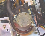
This is the standard engine driven fuel pump for our planes. It's highly reliable and is the only fuel pump in use on many planes. It's also called a "pulse pump" because it is operated by pulses from the engine crankcase. Check valves are built into the pump so no external ones are needed. The engine pulses operate a large, thin, plastic diaphragm inside the pump housing.
Engine crankcase pressure increases or decreases due to a piston's downward or upward travel in it's cylinder. This pressure is transferred to the Mikuni pump via a pulse line which is similar to fuel line. The pulse line connects between a port on the engine crankcase and a port on the pump housing. The crankcase pressure then moves the diaphragm in the pump, which, in turn, draws in or pushes out fuel through the check valves. This process is repeated thousands of times per minute. The pump output feeds the carburetor bowls on the engine. |
|
Click to Enlarge |
There are several models of Mikuni pumps, some for single carb engines and some for dual carbs. There are round shaped ones (high output) and square shaped ones (standard output). The mounting is not critical, with one exception, and the location chosen is usually fairly close to the pressure port on the engine. This is to keep the pulse line as short as possible. The maximum length recommended is about 16 inches.
Click to enlarge. |
|
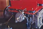
The Mikuni pump should NOT be mounted to the engine itself because of problems caused by the vibration and shaking of the engine. It should be mounted to the root tube or to the heavy duty aluminum "L" bracket above the isolation plate (with the 6 rubber mounts in it) which is bolted to the engine crankcase.
This photo shows one method for mounting the Mikuni pump. Also in this photo you can see the nipple at the center of the pump where the pulse line is to be connected. |
Periodic rebuilds:
Rebuilding is up to the individual. Some folks rebuild annually; some every two or three years. Rebuild kits are available at reasonable prices so it's not uncommon to see it done annually. Some folks have reported flying many hours and many years without rebuilding the pump. It's really just up to you and your comfort level.
6. The Squeeze Bulb (System suggested by QCU, "the factory")
Many builders elect to use a simple hand-operated squeeze bulb in lieu of an electric pump for pumping fuel up to the carburetor bowls. The bulbs are simple, inexpensive, and require no electrical connections. They are also much lighter than electrically-driven auxiliary pumps.
Click to enlarge. |
|
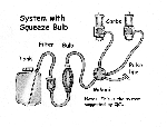
The fuel system suggested by QCU (Quad City Ultralights, "the factory") includes a squeeze bulb and is just one notch more complex than the simple system we described earlier in Section 1. Click Here to see a diagram of this system. As you can see, the bulb is placed in series with the fuel line right after the filter next to the tank. In normal operation, the engine-driven Mikuni draws fuel through the squeeze bulb.
The bulb contains two "ball-in-a-cage" check valves. The outlet valve opens when the bulb is squeezed and allows fuel to flow upward toward the Mikuni and the carburetor bowls. At the same time, the inlet valve is forced shut, preventing backflow toward the tank. When the bulb is released, the rubbery material springs out, closing the outlet valve and opening the inlet valve. Fuel from the tank then flows into the bulb, readying it for the next squeeze. |
All that is required to fill the carburetor bowls is for the pilot to give the bulb a squeeze or two. However, a bit of caution is due here: don't over do it. Overly aggressive or excessive use of the bulb can produce too much fuel pressure at the inlet to the carburetor and overcome the inlet valve to the float bowls. In the extreme, this can flood the carburetor and perhaps cause raw fuel to run into the cylinders or out the air filter.
Whether a squeeze bulb should ever appear in a fuel system is a point of argument that has been around for years and which will not go away. Here are the major issues:
First, not all squeeze bulbs are of the same quality. Some develop minute cracks that allow air to enter the system, producing a disconcerting string of bubbles in the fuel line. Some are said to have been bad, right out of the box.
There have been problems reported with the check valves. If the spring pressure exerted on the inlet valve is excessive, the Mikuni may not be able to draw fuel from the tank past this valve. Also, in many cases, it is not impossible for the inlet ball to come out of the cage and block the outlet port of the bulb, shutting off fuel flow to the engine. For this to occur, however, the bulb would have to be mounted with the outlet port lower than the inlet port, which is a good reason not to mount it this way.
Some bulbs have allegedly introduced trash and debris into the system from the interior of the bulb. This is particularly undesirable, because there may not be a fuel filter after the bulb to catch the debris before it reaches the Mikuni and the carburetors. Further, if you install a filter after the squeeze bulb, you are adding another component that the Mikuni must "pull through" in order to draw fuel from the tank.
Some builders install a fuel line in parallel with the bulb so that in normal operation, the Mikuni draws fuel through this parallel line rather than through the bulb. This eliminates the possibility that a blockage within the bulb could shut off fuel flow to the engine. However, this requires that the parallel line be "pinched off " (so that fuel cannot flow through it) while the bulb is being squeezed to pump fuel up to the carbs. |
|
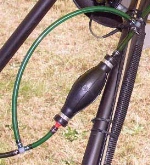 A pinch line in parallel with a squeeze bulb installed on a Quicksilver.Click to Enlarge A pinch line in parallel with a squeeze bulb installed on a Quicksilver.Click to Enlarge |
7. Facet Electric Pump Model 40105
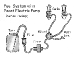
This pump is generally used, in lieu of a squeeze bulb, as a secondary, auxiliary pump for filling the fuel lines, for pressurizing the lines when a primer solenoid is used, and as a backup fuel pump in case the engine-driven Mikuni should fail.
Several models are made, but the one we use is the low-pressure Model 40105. It produces a pressure of 2 psi at its maximum fuel flow rate, and a pressure of 4 psi when it pumps against a closed line. Its output pressure is not adjustable.
The pump runs continuously with a tick-tick-tick sound as long as 12 VDC is applied to the two wires. As pressure builds up in the system, the tick-tick-tick gradually changes to more of a subdued thump-thump-thump. It does not stop running when it builds pressure up to its rated value as some electric pumps do.
The pumps are available from many of the aircraft parts suppliers and even NAPA stores (part # 610-1051). Prices vary from just under $30 to nearly $40 depending on where you shop. |
|
Click to Enlarge |
Two barb fittings will need to be purchased to connect the 1/4" fuel lines to the pump. These can be obtained at a local auto parts or hardware store. What you are looking for:
Two Brass, 1/8 inch NPT, 1/4 inch hose barbs.
The opening through which the fuel flows is 1/8 inch in diameter. The barb is intended for use with a fuel line whose inside diameter is 1/4 inch. NPT stands for National Pipe Thread.
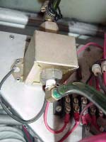
A Facet electric fuel pump
installed on a Challenger. |
|

A Facet pump installed
on another type plane. |
|
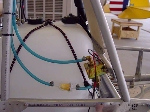
Fuel tank, Facet pump, and fuel
lines installed on a Challenger. |
Click on images to enlarge.
8. Sealing Threaded Connections ( as appear on the Facet pump )
The first question that will arise when you go to install the hose barbs on the Facet is, "What type of thread sealer do I use?"
The body of the Facet is made of brass. If you have hose barbs that are also brass, no sealer is required. The threads, being pipe threads, are tapered and the design of the thread is such that they create an interference fit as you torque them down. But, you must torque them down tight, really tight.
No, you don't need a torque wrench for this. If you hold the body of the Facet with a wrench that is about a foot long, and then use a smaller wrench, about 6 inches long, to turn the barb, the proper torque will be just about "all you can apply" by hand, assuming you are of average strength.
The barb will begin to bind after only about 3 or 4 threads are screwed into the port on the Facet. This is normal. Then use the wrenches. There will be lots of threads still showing when you get it tight enough. Don't try to screw it all the way in. It's not impossible to split the body of the Facet if you really, really force it.
Now, if this suggestion makes you a bit uncomfortable, just remember that if you don't get it tight enough on the first try, and it leaks (unlikely), you can always go back and give it another twist without having to remove or even loosen the barb.
Teflon tape:
Many builders use Teflon tape successfully as a sealant. However, you must be very careful with this. What happens is that the threads tend to cut the tape into shreds as you screw the barb in. This happens inside the threaded portion where you can't see it. If these shreds then work their way to the front of the ingoing thread as you insert the barb, they can detach and become debris in the fuel lines.
Also, if you use the tape, be sure that it doesn't lap down over the front, flat face of the threaded portion of the fitting. If this happens, the overlapping part will most certainly be sheared off as you insert the fitting, and you will then have a significant chunk of tape meandering around inside your fuel system.
And, of course, everybody knows that when you apply the tape to the threads, wrap the tape on the threads in such a direction that when the barb is screwed into the Facet, the tape tends to get wrapped more tightly. Specifically, with the threaded end pointing away from you, ready to go into the Facet, the tape should wrap counterclockwise.
Paste-type sealants:
For this application at least, we do not recommend the use of any type of paste-type sealants, pipe dope, the kind you squeeze out of a tube and then smear onto the threads. Some may be OK and have been used, but others are not. If you get the wrong kind, you could have problems. Why take a chance, especially when using no sealant at all is just fine?
Non-brass hose barbs:
Hose barbs made of metal other than brass are available, as are those made of "plastic." We are not aware of any obvious reason why these can't be used, except, do not use nylon. Nylon tends to harden and get brittle when exposed to gasoline.
Conventional wisdom holds that you do not need a sealant for pipe threads where both parts are made of the same metal. However, here, since the assumption is that we're not using brass, a sealant should be used. We suggest Teflon tape, being aware of the pitfalls associated with the tape.
Due to the moldable nature of even the hardest plastic (The word "plastic," in materials science even means moldable of capable of being deformed.), it is unlikely that any sealant will be required. The plastic will deform enough to mold to the shape of the matching threads and effect a seal. Remember, go easy when you screw these in. Don't break the barb or twist it so much that the whole body of the fitting is twisted all out of shape. That just isn't required.
9. Series or Parallel Hookup ?
A never-ending debate surrounds the question of whether it is best to connect an auxiliary fuel pump in series or in parallel with the engine-driven Mikuni. As you may expect, each method has its advantages and disadvantages. In this section, we describe each one and attempt to give the advantages and disadvantages commonly attributed to each one.
SERIES
A diagram of a series hook up is shown in Section 7 of this article.
PRO: It's very simple to hook up. The fuel comes out of the tank, goes through a filter, through the Facet, then to the Mikuni and on to the carburetor bowls. A switch on the dash is connected to 12 volts to run the Facet pump when desired. Fuel flows through both pumps no matter which pump is running. The installed system looks neat and clean. Fewer connections mean fewer possibilities of air leaks due to faulty connections.
CON: It uses a single point fuel pickup so if something blocked the fuel lines or failed in the system at any given point, it could fail the entire system. The pump pressures are additive which, although not normally a consideration, could possibly overpower the float valve and cause flooding of the carb bowls. The Bing carb bowl floats are set for about 7.3 psi, give or take a bit.
PARALLEL
PRO: Should something fail in the Mikuni lines, the Facet would be unaffected. If one installs a separate pickup tube for the Facet (backup system), you would have true redundancy in the fuel system.
Since the two systems are completely independent, the main could fail or be blocked and the backup would not be affected. Fuel pressures are not additive but the system capacity is additive when both pumps are running.
CON: It's more complex to hook up. If using a single pickup tube, the fuel comes out of the tank, goes to a filter, then a tee connector which splits the fuel supply to the Facet and the Mikuni pumps. The fuel joins again in a tee connector at the output of both pumps and on to the carbs. If using a separate pickup tube for the Facet pump, the fuel comes out of the tank in a separate pickup tube, goes to a separate filter and to the Facet pump. It's output then joins together at with output of the Mikuni in a tee connector and on to the carbs.

Click to enlarge. |
|
Some, but not all, parallel systems look like a rat's nest of fuel lines ... very cluttered due to the many connections. Those with separate pickup tubes are much less cluttered than those using a single pickup tube. The multiple connections also introduce a greater possibility of air leaks due to faulty connections.
Many folks using a secondary fuel system run both at all times for "peace of mind". This is unnecessary due to the Mikuni's extremely high reliability. Another reason not to do so is that if the main pump failed and both pumps were running, the main pump's failure would never be noticed. Secondary systems are generally used for takeoff and landing ... or flying "low and slow" as we are given to do on occasion. :-) |
In the parallel system, check valves must be present in the circuit in line with each pump. This prevents the flow from one pump from simply returning to the tank by way of the other pump. Fortunately, however, both the Mikuni and the Facet pumps have built-in check valves so that additional valves are not needed. But if you use an auxillary pump other than the Facet, be sure to take the matter of the check valve into consideration.
10. Primer Systems

Click to enlarge. |
|
A primer system allows the pilot to squirt raw fuel directly into the intake manifold or into the barrel of the carburetor to aid in starting a cold engine. The primer serves the same purpose as the choke or enrichener, namely that of producing a very rich mixture during startup. Normally, either the primer or the choke will be used. Both are seldom required.
In the cockpit, the "primer" is a small, syringe-like pump that is mounted on the instrument panel, or maybe elsewhere, within reach of the pilot. Pulling the primer knob outward draws fuel into the barrel of the primer. Pushing it in squirts this fuel into the primer port on the carburetor, or into a special port on the intake manifold. |
|
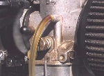
Capped-off primer port on a Bing
Click to Enlarge |

Click to enlarge. |
|
The fuel lines that run to the primer pump are smaller than the regular fuel lines that carry fuel from the tank to the Mikuni and to the carburetor. Primer line is only 1/8 inch in (inside) diameter whereas regular fuel line is 1/4 inch ID.
The primer line that delivers fuel to the primer pump is usually Tee'd into the regular fuel line right after the filter next to the tank. Special reduction Tees are available to facilitate tapping 1/8 inch primer lines into the regular 1/4 inch lines. |
|
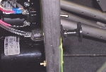
Side view of primer pump
Click to Enlarge |
Some builders and pilots do not like the idea of having fuel lines running through the cockpit area. The concern is that a primer line may fail and spew raw fuel into the cockpit, which, if ignited, would make for an unpleasant situation, to say the least. For this reason, they elect not to use a primer. Also, a primer is not essential anyway as many pilots report satisfactory starting using only the enrichener circuit that is built into the carburetor.
Electrically operated solenoid valve used as a primer:
This system is favored by some, in part because it avoids the necessity of running primer lines to the cockpit area. Also, some like the convenience of having "push button" priming capability as the solenoid is much faster-acting than the manual push-pull primer pump.
There is a significant difference in the plumbing of the two systems. Because the solenoid valve is only an electrically-operated valve, and not a pump, the fuel source for the primer circuit must be pressurized. Normally, this system is used in conjunction with an electric auxiliary pump such as the Facet. The primer line is Tee'd into the regular line between the auxiliary pump and the Mikuni.
The starting procedure involves, first, turning the auxiliary pump ON to build up pressure in the lines. Then, just tap the dash-mounted primer pushbutton to momentarily open the primer solenoid valve. This allows fuel to flow through the primer lines to the primer port of the carburetor. Experience dictates how much of a push and how many pushes of the button are required in various situations.
11. Carburetor Bowl, Floats, and Inlet Valve
The carburetor bowl, or float bowl, attaches to the very bottom of the carburetor. The bowl serves as a reservoir from which the fuel circuits inside the carburetor draw fuel. It is easily removed by rotating a rather strong wire bail to the side. Many pilots remove the bowl frequently to check the fuel level and look for water or debris that may have found its way into the system.
The bowl encloses the float assembly, which consists of the floats, the float arm, and a float arm tang that pushes upward against the bottom of the inlet valve poppet. As the fuel level rises in the bowl, being pumped in by the fuel pump, the floats move upward and the float arm tang pushes up against the inlet valve poppet. When the fuel rises to the proper level, the poppet closes against the inlet valve orifice, shutting off the fuel flow into the bowl.
The fuel in the float bowl is not under pressure. The bowl is vented to the atmosphere, or on some Bing carburetors, it is vented to a point near the air inlet. This vent is critical to the operation of the system, and the instructions for the particular carburetor you are using should be followed closely.
The level of fuel in the bowl gives a good indication of the proper or improper operation of the fuel system. A level that is too low may indicate that the fuel pressure at the inlet port of the carburetor is too low, or it might mean that the float arm and tang are out of adjustment, perhaps after having been "adjusted" by a previous owner.
A fuel level that is too high may indicate excessive fuel pressure at the inlet port, or it can reflect a problem with the float assembly or inlet valve. Floats sometimes become saturated so they don't float as high in the fuel, which will cause overfilling of the bowl. The seating surface of the valve poppet may have become hard due to age so that it doesn't seal like it should when it contacts the seat. And, of course, there is always the possibility that a bit of trash could be preventing the poppet from seating correctly.
The level of fuel in the float bowl also affects the fuel-air mixture that the carburetor produces. The venturi effect produced by the rapidly flowing air through the barrel of the carburetor draws the fuel upward from the float bowl. If the level is high, more fuel will be drawn up for the same air flow and a richer mixture will result. If the level is low, less fuel will be drawn up, producing a leaner mixture. Admittedly, the effect may not be pronounced, but for an engine that is very sensitive to small changes in mixture, a small change can sometimes have a significant effect.
Replacement floats and inlet valve poppets are available. It is not a bad idea to replace at least the poppet every year or so as a routine maintenance thing. Also, for some Bing carbs at least, valve poppets are available that have a stronger spring. The use of such a poppet may solve a problem of excessive fuel pressure at the inlet port.
Any adjustment of the tang on the float arm is to be approached with caution. The first question that should arise is, why does it need adjustment in the first place? It may be that there is another problem present, and if so, adjusting the tang or bending the float arms will only compound the difficulties. It is not impossible to ruin an engine with good-intentioned adjusting of the float arms or float arm tang.
If, however, you do decide to adjust the tang, be advised that just a little goes a long way. Bending the tang up or down by a mere ten thousandths of an inch will have a significant effect. After such an adjustment, the fuel level in the bowl must be checked carefully. All in all, it is usually, but not always, unwise to attempt this adjustment.
12. Choke vs. Enrichener
We often refer to "pulling out the choke" in regard to operating a Bing carburetor. In fact, the Bing does not have a "choke" in the true sense of the word.
A classic choke is a butterfly valve located near the air inlet of the carburetor. This butterfly closes when the choke is pulled ON, which restricts the airflow. This produces a lower pressure inside the carburetor barrel and draws more fuel into the airstream, producing a richer mixture. These are still used on small engines for lawnmowers, weed whackers, and so forth.
The counterpart of the choke on a Bing is a separate fuel circuit that adds extra fuel without the use of a butterfly valve. "Pulling out the choke" simply opens the fuel flow into this separate "enrichener" circuit.
All in all, the two accomplish the same thing and no great harm is done by referring to the enrichener as a choke. In fact it's simply a matter of terminology or slang.
13. Fuel Pressure Regulators
First of all, because the pressure produced by the Mikuni fuel pump is well-matched to the inlet pressure requirements of the Bing carburetor, a fuel pressure regulator is seldom if ever needed in a fuel system for a Challenger. However, for purposes of completeness of this article, here's where a fuel pressure regulator might be required.
The float valve on Bing carburetors used on the Rotax 503 and 582 can withstand a maximum fuel pressure of about 7 psi. But not all Bings are this way. Some can withstand a maximum inlet pressure of about 3 psi.
Now, a Mikuni pump typically produces more pressure than this. Further, if an electric auxiliary pump is connected in series with the Mikuni, the pressure can far exceed the allotted 3 psi. In this case, a fuel pressure regulator is required in order to prevent the excess pressure from flooding the float bowls, the carburetor, and everything else.
In the installation, the fuel pressure regulator is installed between the engine-driven fuel pump and the inlet to the carburetor.
Fuel pressure regulators are not all the same. One contributor to this article, faced with excess fuel pressure on a non-Challenger ultralight, encountered two pressure regulators obtained from ultralight parts suppliers that would not function satisfactorily. They reduced the pressure alright, but they restricted the flow rate in the process. This led to fuel starvation at WOT, like on takeoff. Not good!
A pressure regulator that has performed flawlessly for over 100 hours is one made by the Holly Carburetor people for automotive applications. The part number is 12-804. It is adjustable over a range from about 1 to 5 psi.
14. Fuel Pressure Gauges
A fuel pressure gauge is another item that is normally not found on a Challenger. However, if the fuel system on any aircraft has a fuel pressure regulator or other items that may need "dialing in," a fuel pressure gauge is essential, at least at the outset. For example, the Holly regulator referred to above has no indicator to show what the pressure setting is. You turn the screw, test it, turn the screw some more, and test it again, reading the pressure on the fuel pressure gauge each time.
Also, it's a comforting thing to be able to look at the fuel pressure gauge and see that all is well, especially after you have gravitated toward a complex fuel system, perhaps out of necessity.
Fuel pressure gauges can be obtained from auto parts stores, especially those that cater to the "performance" applications. And, they typically cost less than $30.
The installation of a fuel pressure gauge requires a fuel line to run to the gauge, unless it's a sophisticated electronic type with a remote sender. The gauge is Tee'd into the main fuel line between the pressure regulator and the inlet port of the carburetor.
This again brings up the matter of having fuel lines in the cockpit area. However, because the fuel in the line to the gauge is purely static, a restriction can be inserted into the line with an opening little if any larger than a pinhole. In the event of a leak, with the restriction in place, the quantity of fuel actually escaping would be small in comparison to what would escape if a full 1/4 inch line were to fail. The restriction in the line will also serve to reduce the vibration of the needle that sometimes occurs due to the rapid pulses of pressure in the main fuel line.
15. FUEL LINE BUBBLES
Bubbles in the fuel lines are noted to be somewhat common for our Challenger systems. Most folks see them as a single, large bubble at a high point in a fuel line, usually near the Mikuni fuel pump on our systems. Others have seen them so numerous as to believe there was a serious air leak in the system. They can be caused by poor line connections at the brass fittings or by negative pressure due to fuel flow restrictions such as too small a pickup tube, dirty fuel filter, or sharp bends in the fuel lines.
A few bubbles should present no problems as they usually are pumped on through the system and into the carb fuel bowls where they vent naturally. However, an abnormally large amount of bubbles can actually prevent fuel flow due to there being so much "air" in the system that the Mikuni pump can't move enough fuel to the carburetors. In this case, the engine quits due to lack of fuel. It's a bit like an air bubble in a car's brake system. The bubble will allow the brake pedal to go to the floor without actuating the brakes. This happens because the air is compressible whereas liquid is not.
One way to tell if there are any air leaks is to pressurize the fuel system. Some leak detector solution can be used to find the leaks. Children's bubble-blowing liquid is good for this or you can make your own with some dish washing liquid and water. At any rate, squirt it on a connection and see if it bubbles up into a growing pile of bubbles. If it does, you've found a leak.
Another way to tell, if you aren't able to pressurize the system, is to first make sure the carb fuel bowls are full. Then run the engine and shut off the fuel line at the tank's pickup tube, or pinch it off somewhere if there's no fuel shutoff valve in the system. Bubbles will appear at the leak due to the suction of the fuel pump bringing air into the system.
Bubbles can also occur if there is enough negative pressure to bring them out of the fuel. A fuel shutoff valve will help you troubleshoot this problem. Again, making sure the fuel bowls are full, start and run the engine. Shut off the fuel at the tank and see if the bubbles stop. If they do, you not only know that the fuel system is airtight, but you know the bubbles are coming out of the fuel as in a vapor lock situation.
Our systems aren't near a hot enough heat source to cause vapor lock as we know it in automotive systems. Therefore, heat shields or fire sleeves are not a fix for the problem.
Some folks have fixed bubble problems by placing the fuel filters after the pump or on the positive pressure side of the pump. This lessens any negative pressure caused by the restrictive nature of filters, connecting elbows, and/or bends in the fuel line. A larger pickup tube has also been known to help, again due to its being less restrictive. At least one individual is known to have replaced his Mikuni pump with a Facet electric pump in addition to his Facet backup pump. While he still has bubbles due to negative pressures, the electric pumps are not affected by them.
16. Throttle Mechanism
Though technically speaking, the throttle mechanism isn't part of your fuel system, it does control fuel flow and as such can be a critical component. The factory system is a fairly simple piece of mechanism and is relatively trouble free.
The single place Challenger has only a single throttle control. If you have dual carbs, there are dual control cables connected to it. Make sure the cables don't bind due to any sharp bends on their way back to the carburetors. The cables should have a fairly "straight shot" to the carbs. As they come out of the area in front of the engine, they should be located up toward the root tube so they can have a gentle sweep down to the carbs' connection points.
The two place Challenger will have two throttle controls, one for each cockpit. The control cables are connected to the rear seat control, and the front seat control connects to the rear seat control with a sheathed "rod" or very stiff control cable. Set screws keep the cable connected tightly to each throttle control assembly.
There has been a post or two about the set screws loosening up. One fix is to bend the cable rod ends down somewhat after inserting it into it's keeper. This would make it difficult if not impossible for the cable rod to slip out should the set screw loosen up. Another fix is to also use some red loctite on the set screws.
17. Cleaning the Fuel System
Flushing the tank
If the tank is removed from the plane, it's a simple matter of swishing some fuel around in the tank and dumping out any sediment or debris that happens to be in it. On the plane, it will take more effort due to limited working space, but it can still be cleaned out rather easily. One method is to use a squeeze bulb on the end of a 2' long, 1/4" metal tube. Place the tube into the sump area or corners to be cleaned and squeeze the bulb. You have a vacuum cleaning system. A long-handled brush may be used to loosen any debris that won't come up easily with this vacuum system.
Purging the fuel system
A new fuel system may have construction debris in it especially if the fuel tank has been drilled and fitted with a fuel quantity sender. To clean out the tank, simply turn it upside down to get loose drill tailings out, or use air pressure or a vacuum to either blow or suck them out.
The main entry point for any debris getting into the fuel system will be the tank itself. This assumes that no teflon tape has been used improperly in the system, no automotive, black-rubber hoses or anything else not impervious to our fuel and which may be subject to deterioation over time. After being sure the tank is clean, there should be little if any chance of debris entering the system at any point other than the fuel filler opening. The usual recommended location for a fuel filter is next "in line" from the fuel tank.
Filling the fuel lines
Either a squeeze bulb or an electric fuel pump may be used to fill the fuel lines and subesequently the fuel bowls on the carbs. Another way to get the lines filled if either of those methods is not used, is to remove each carburetor fuel bowl, fill them manually, then put them back on and start the engine. This should let your engine run long enough to allow the pulse pump to fill the lines and get fuel to the carbs which will then replenish the fuel bowls and keep the engine running.
by: Advisory Committee Members
|
