This article was written by an independent author. Views expressed in this article may not align 100% with the views of the Challenger Advisory Committee.
In the Experimental Amateur Built (EAB) and Ultralight world, fuel delivery systems are probably the single leading cause of engine-outs. As is the nature of EAB and Ultralights, the sky is the limit on fuel delivery system designs. I have seen all kinds of wild designs come through my shop over the past decade or so. Some were very well thought out, but many were a disaster waiting to happen, or had already happened. I also receive a high volume of calls on this subject and consequently spend a lot of time on the phone with customers discussing this. I finally decided that a comprehensive article on the subject would be very valuable to the EAB and Ultralight community, and hopefully prevent a few accidents!
The fuel delivery system is the sum total of all of the components involved in the process of getting fuel to the carbs or fuel injection system. There are several components involved in this system and we will discuss each one thoroughly. We will also discuss proper design and maintenance of the system. Many accidents are caused by poor fuel delivery system design, but many more are caused by lack of maintenance of the fuel delivery system.
Fuel Tanks
Let’s begin with the fuel tank. While not a component that is the subject of discussion very often, it is nonetheless an important part of the system and has been the cause of several failures that I have found.
The first consideration of the fuel tank is the material that it is constructed of. Generally speaking, I have seen three different types of materials used to construct tanks.
First is fiberglass. In the old days, fiberglass was a common option and it worked well. However, around the time when plaid pants were beginning to go out of style and side burns were being shaved off, some genius came up with the idea of putting moonshine in gasoline. Whoever he was, he must have been a politician and owned a distillery because now it is almost universally mandated that gasoline contain at least 10% ethanol and soon may go to 15%. While that makes little difference to most cars on the road, it does cause some issues for airplanes.
When gasoline-containing ethanol is put in an older fiberglass tank, it begins a reaction that gradually dissolves the fiberglass into a powdery white dust. This process will not only cause the tank to begin leaking at some point, but the residue will also plug fuel filters, and in some cases pass through filters and cause problems elsewhere in the engine’s fuel system. If you have a fiberglass tank, check with the manufacturer and see if it is ethanol compliant. If it is not, you only have two options: use avgas or auto gas that you are absolutely certain does not contain ethanol. The only other option is to replace the tank. This is a real problem for many owners of Kitfox and the like who have fiberglass wing tanks built into the wing. The new tanks are available, but it’s a lot of work to replace them.
If your tank is aluminum, you have no worries of fuel reacting with it. The only problems of aluminum tanks are that they can sometimes crack due to vibration and leak, and they are more susceptible to condensation. To prevent condensation, store the airplane with a full tank of fuel. The less air you have in the tank, the less condensation will be present.
If your tank is polyethylene, you have no worries. These tanks are very reliable, have no reaction to just about any substance, and develop very little condensation. The one caution I have with them is that if you ever have a leak in one from wear or builder error, do not attempt to patch it, replace it. I have never found a material that will both adhere to polyethylene and be resistant to ethanol gasoline for the long term. If the patch comes loose, not only will it leak, but the patch material may get into the fuel delivery system and cause a blockage and its failure. It’s not worth it. Replace it. The tanks are not that expensive!
The next consideration in the tank area is how to get fuel out of it. The two options are: draw it out from the top via a pickup hose or tube, or pull it out from the bottom. The factory provided Challenger tank, for example, uses a copper pickup tube from the top of the tank. The tube stays just off the bottom so that water and debris should not be picked up. The main disadvantage to this setup is that there is no sump provided to drain water and debris from the bottom of the tank. However, a sump could easily be added.
On a side note:
There is one other safety concern with a Challenger factory-style fuel pickup installation. And that is when the aircraft is flown in very cold weather while using ethanol gasoline, the water absorbed in the ethanol may begin to create frost on the inside of the pickup tube and can actually close it off which would probably cause an engine failure.
If one is concerned about this possibility the only option is to pull the fuel out of the tank at the lowest point, ideally at a sizable downward indentation in the bottom of the tank (referred to as the sump). Not all tanks have that indentation. In that case the outlet will need to be positioned at the lowest point in the tank when the tank is in the normal flight attitude. In some installations it may be advantageous to use two ports and “T” them together. For instance if the tank is of an irregular shape or maybe the aircraft’s attitude on the ground is different than in flight, such as might be the case with a taildragger. It is important that the port is at the lowest point when on the ground to drain water, but at the lowest point in flight to be able to access fuel at all times.
Now, with any type of tank, another topic of discussion is how to facilitate a port in the tank. In an aluminum tank a welded pipe thread port is often used and works well. However, that is not an option in fiberglass and poly.
 Occasionally a fiberglass or poly
tank will have a threaded port molded into it, and that is fine as well. If neither
of these are an option, another way to accomplish this in a safe and reliable
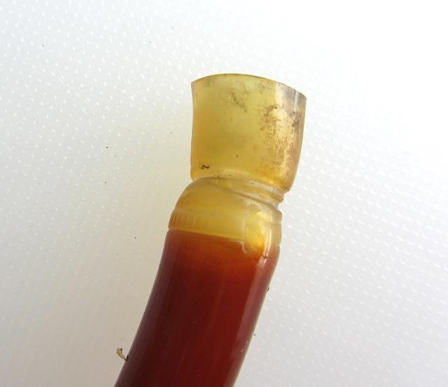
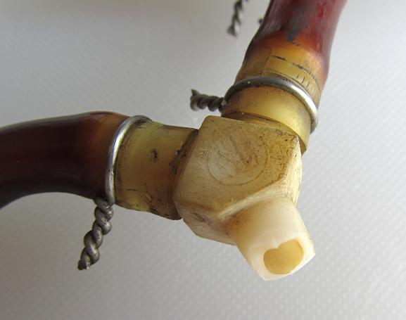
manner is to use a grommet and elbow. In this method a ˝ inch hole is cut in
the tank wall, a special grommet is inserted into the hole, and then an elbow
or elbow with a valve which can come in handy for maintenance purposes, is
inserted into the grommet.
Occasionally a fiberglass or poly
tank will have a threaded port molded into it, and that is fine as well. If neither
of these are an option, another way to accomplish this in a safe and reliable
manner is to use a grommet and elbow. In this method a ˝ inch hole is cut in
the tank wall, a special grommet is inserted into the hole, and then an elbow
or elbow with a valve which can come in handy for maintenance purposes, is
inserted into the grommet.


Many people may quiver at the thought of this, but it  actually is a very simple, easy and
reliable solution. The key to this installation is to use a rotary cutter to
create the hole. A spiral drill bit will create a triangle-shaped hole in thin
material and it is likely to leak. A rotary cutter
will makes an exactly round, nice smooth cut hole and you will have no
issues with sealing. This method can be used on poly, fiberglass, or aluminum.
actually is a very simple, easy and
reliable solution. The key to this installation is to use a rotary cutter to
create the hole. A spiral drill bit will create a triangle-shaped hole in thin
material and it is likely to leak. A rotary cutter
will makes an exactly round, nice smooth cut hole and you will have no
issues with sealing. This method can be used on poly, fiberglass, or aluminum.
Filters
Another critical component of the fuel delivery system is the filter. There are various ways to filter fuel in an aircraft fuel system, but in our applications there are two that are the most common.
The first is a gascolator. A gascolator combines a sediment bowl for water and debris to drop out and be drained, along with a stainless steel mesh to filter out anything that did not drop out in the sediment bowl. Gascolators are also common on certificated aircraft.
 The other form of filtration
commonly used in EAB and ultralight applications is
an inline fuel filter. There are many types of inline fuel filters and there
are pros and cons to each. The type of fuel filter that I recommend has a
transparent plastic housing to allow for easy inspection, a paper or stainless
mesh with plenty of surface area so as not to clog easily as the filtration
unit, and good firm barbs on the ports for the hose for a secure seal. Sintered
Bronze is also a good filtration media, but the bronze filters I have seen do
not have enough capacity to be considered safe for aviation. Beware of filters
that screw together such as the Purolator.
They have been known to unscrew in flight and cause a failure.
The other form of filtration
commonly used in EAB and ultralight applications is
an inline fuel filter. There are many types of inline fuel filters and there
are pros and cons to each. The type of fuel filter that I recommend has a
transparent plastic housing to allow for easy inspection, a paper or stainless
mesh with plenty of surface area so as not to clog easily as the filtration
unit, and good firm barbs on the ports for the hose for a secure seal. Sintered
Bronze is also a good filtration media, but the bronze filters I have seen do
not have enough capacity to be considered safe for aviation. Beware of filters
that screw together such as the Purolator.
They have been known to unscrew in flight and cause a failure.
Inline fuel filters should be inspected on every preflight. It is normal for them to only have a slight amount of fuel in them, even while the engine is in operation. Make sure that there is little or no debris in them and replace them often, at the very least at every annual condition inspection.
One other consideration on the subject of filters is the placement of them. If your fuel delivery system uses a pump or multiple pumps, there should be a filter before each pump. If you have two pumps for redundancy, use two filters as well.
Pumps
The next component, the fuel pump, seems to be the one that people are the most concerned about failing in the fuel delivery system. In reality, the fuel pump itself is seldom the cause of fuel starvation. When the fuel pump does fail, it almost always from not maintaining it, or debris being allowed to enter it. As discussed previously, it is very important to place a filter or gascolator on the inlet side of the fuel pump to prevent debris from entering the pump.
There are several types of pumps used in EAB and Ultralight aircraft. The most common on two-stroke and some four-stroke applications is a diaphragm pump, or pulse pump. The diaphragm pump uses the pulse of the crankcase pressure to move the internal diaphragm back and forth. This action, combined with two check valves, draws fuel into the pump then pushes it out the output side. These pumps are very effective and very reliable. However, there are three common ways this pump can fail.
The first is the diaphragm or check valves fail from an extended service life. This is uncommon and easily prevented by rebuilding or replacing the pump at least every other year.
The second cause of failure is debris getting into the pump and sticking in a check valve preventing it from sealing. This is easily prevented by proper filtration of the fuel prior to entering the fuel pump.
The third cause of failure is less known and deserves some discussion. It’s called “hydro locking”. Hydro locking can occur when a pulse driven diaphragm pump is mounted physically lower than the crankcase pulse port on the engine. Oil and/or fuel from the engine crankcase gradually get expelled into the pulse line and runs downhill into the fuel pump. This oil and fuel can accumulate behind the pumps diaphragm and will eventually prevent the diaphragm from moving and the pump stops moving fuel.
There are two ways to prevent this. The best way is to mount the pump higher than the crankcase pulse port. This way any fuel or oil expelled into the pulse line will run back down into the crankcase.
In some applications it is not practical to install the pump higher than the engine. In these situations a very small hole should be drilled in the lowest point of the pump body on the pulse side if mounted vertically, or in the pulse elbow if mounted horizontally, to drain out that fuel and/or oil.
Another consideration with pulse pumps is that the pulse line should be 12” or less in length. The longer it is, the less effective the pulse will be. The pulse line also should be fairly rigid. I have found that normal blue urethane fuel line works just fine if kept to the 12” max length!
The next type of fuel pump used on aviation engines and some automotive conversions is known as an engine driven mechanical pump. These pumps generally work similar to a diaphragm pump except they use a mechanical movement, such as an arm riding on a cam lobe, to operate a diaphragm. These pumps are similar to diaphragm pumps in that they must be protected from debris, and they need to be replaced or rebuilt periodically according to the manufacturer’s recommendation!
Another common fuel pump in EAB and Ultralight aircraft is the low pressure electric pump or electronic pump. The most common of these found in aircraft are the Facet brand. The Facet pumps use an electronic pulse to pump the fuel. Facet makes a large variety of pumps. From my experience, the only Facet pumps I would consider using on aircraft are the gold block style. I have seen several failures of the Posi-flow type and would not recommend those.
There are several pressure ratings on the gold block style pumps ranging from 1.5 psi to 6 psi, as well as flow ratings from 15 gph to 30 gph. For slide bore carbs, I would recommend the Facet part number 40105 pump. It has 2.5 - 4.5 psi range, and 30 gph. This is a great pump for most any carbureted engine. It is, however, generally considered to be unsafe to rely solely on a single electric pump. An ideal scenario is to have a diaphragm or mechanical pump as the primary and an electric pump as a backup.
One other type of fuel pump found in aircraft is the high pressure electric pump. This type of pump uses an electric motor and impeller to pump fuel. This type of pump is used in electronic fuel injection systems, and is most commonly found in Hirth two stroke applications and some automotive conversions. Fuel pressures in these applications are generally in the 50-psi range and require special considerations. These pumps draw more electrical power than a Facet pump, often between 5 - 10 amps at 14V. Special care must be taken in the circuit provided for these pumps. Ensure that the wire is sufficient to carry the current, that circuit protection is adequate to handle the load, and that the charging system of the engine is sufficient to provide for the load of the pump and all of the other electrical loads.
Because of the complexity of designing a dual pump configuration with these systems it is common for these systems to have only one pump and is therefore critical that it does not fail. Also, with 50 psi, special fuel lines and clamps are required. We will discuss that more in the next section.


Fuel Line
Another commonly debated component of a fuel delivery system is the fuel line. There are several types of fuel line used in EAB and Ultralight aircraft.
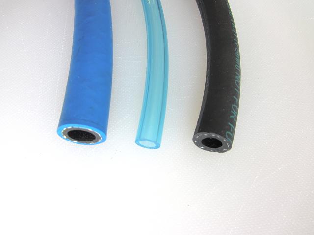 Probably the most common is the
blue urethane fuel line also common in the marine industry. It performs well in
our application, is resistant to ethanol, is lightweight, and has the added
benefit of being transparent. It is currently my first choice for carbureted
engines. It is important when using urethane lines to replace them every year.
Probably the most common is the
blue urethane fuel line also common in the marine industry. It performs well in
our application, is resistant to ethanol, is lightweight, and has the added
benefit of being transparent. It is currently my first choice for carbureted
engines. It is important when using urethane lines to replace them every year.
Another common fuel line used in our application is automotive style rubber hose. This can be obtained at your local auto parts store. There are many brands available on the market, however not all are created equal. My experience with regular automotive line is that it tends to crack and weather quickly when exposed to the elements. When I experimented with this type of line I was very disappointed, as I never knew how long a line would go before it failed. In the end I came to feel there must be better quality options available.
Yet another type of fuel line that has really only become common in the last 5-10 years is fuel injection hose. This type of fuel hose is rated for at least 50 psi, and usually substantially more. It has a liner inside it that is resistant to ethanol. If you are using an engine with EFI, you must use this type of hose, and special clamps that we will discuss in the next section.
Fuel injection hose may also be a very good option for a more durable fuel line on carbureted engines. The main drawback to this type of line is that it is expensive, currently (2013) in the $4 per foot range.
One other noteworthy consideration on all of these fuel lines is that the inside of the lines are not necessarily the same material as the exterior and may not exhibit the same resistance to alcohol or other chemicals found in fuel. This becomes very important if the fuel hose is used inside a fuel tank for a pickup line. Beware that any hose you use inside a fuel tank will likely have a very short service life and needs to be checked and possibly replaced often. These are out of sight and often forgotten about.
Fuel Line Clamps
Another commonly debated fuel delivery system component is the clamp. This is a subject that certainly deserves a discussion. There are many different styles of clamps or clamping methods used on EAB and Ultralight aircraft.

The first one that many inexperienced builders will grab is the worm drive hose clamp common in the automotive industry. While these clamps are a great choice for larger hoses in cooling systems, they are a very poor choice for small lines in the fuel system. The first problem with them in small sizes is that they tend to become out-of-round quickly when they are tightened. A clamp that is not round will not seal well on a round hose and barb. The next problem with them is that many people tend to over tighten them causing them to cut into the exterior of the fuel line. I do not recommend using worm drive clamps on fuel lines at all, there are better options.
 Another common clamp is the plastic
tooth type clamp. These work fairly well, but are a real hassle to remove and
tend to get expensive. They are also somewhat bulky in confined areas.
Another common clamp is the plastic
tooth type clamp. These work fairly well, but are a real hassle to remove and
tend to get expensive. They are also somewhat bulky in confined areas.
Yet another clamping method is to wrap two wraps of safety wire around a hose and twist it tight. This method is somewhat effective, but there is so little surface area on safety wire that it will cut into the hose rather than compress it. It is a tedious process to safety wire each hose connection as well, especially when those hoses need replaced annually.

Still another method is the use of small wire ties. This method also suffers from the problem of becoming out-of-round in small diameters. While it may help prevent a hose from coming off a barb, it does little to affect a seal. They can also be tedious to install in confined areas.

Another form of clamp that I really like is the spring steel clamp. Squeezing the end tabs with pliers, sliding it into place on the hose, and releasing it will install this clamp. The spring tension in the steel will provide uniform pressure on the hose and will actually adjust itself as the hose expands and contracts with temperature changes. When the correct size clamp is used these clamps cannot be under or over tightened. They work wonderfully on Ľ” Urethane fuel lines as well as on high quality automotive style fuel lines. These clamps are inexpensive, easy to install and can be used over and over again.
There is one other style of clamp that is specified for  use on the Hirth electric fuel
injection (EFI) systems and might also be a great solution in other applications.
These are the crimp type clamps. They are fairly expensive, can only be used
one time, and require a special tool to crimp. However, these clamps do stay
very round, have a good surface area to compress the hose, and promotes an
outstanding seal even at 50 psi.
use on the Hirth electric fuel
injection (EFI) systems and might also be a great solution in other applications.
These are the crimp type clamps. They are fairly expensive, can only be used
one time, and require a special tool to crimp. However, these clamps do stay
very round, have a good surface area to compress the hose, and promotes an
outstanding seal even at 50 psi.
Fittings
Fuel line fittings also seem to be a debated topic in
aviation circles. While GA airplanes tend to use flare type fittings, to save
weight and cost, most light EAB and ultralight aircraft use barbed fittings.
There are two factors in fuel line fittings that I believe should be taken into
consideration.
The first factor is the material that the fittings are made of. Two material types are available in fuel line fittings, metal and various types of plastic. Metal, usually aluminum or brass, is the more durable and reliable but are heavier and costs more. With the plastic fittings there is no real way to know the compound that is used and it’s resistance to alcohol and other chemicals in gasoline. Some of them tend to hold up well, while others tend to get brittle, develop cracks that leak or simply snap in two.
The second concern is the style of the barb design. There are various designs in hose barbs, but generally they fall into two categories, rounded and sharp.
Mikuni fuel pumps are a good example of rounded barbs. Rounded barbs are much more user-friendly than the sharp barbs. They normally allow a hose to be slipped on or off without damaging it. To prevent leakage on these rounded barbs it’s more important to have a reliable clamp. With a sharp barbed fitting there will often be multiple barbs, and the edges of the barb are sharp and directional. This allows the hose to slide over the barb reasonably easy, but is very difficult to remove without cutting the hose.

With blue urethane hose on a sharp barbed metal fitting, it is probably unnecessary to use a clamping device at all. There is no way a 2-6 psi pressure will ever overcome a sharp barb. The hose connection will remain secure until way beyond the useful service life of the hose. To test this theory, install a dry new urethane hose onto a sharp barb fitting and attempt to remove it by pulling on it. Good luck! Don’t scrape your knuckles when the hose finally tears in two!
My recommendation is to not take any chances. Use only metal fittings. The fuel delivery system is too critical to try to save money and/or weight. Metal fittings can be used over and over while plastic fittings should be replaced annually when replacing the fuel hose, so in the end it may be less expensive to use metal anyway.
Dual Pump Systems
Now that we have covered the basic components of a fuel delivery system, let’s consider some design aspects of the system. In any aspect of aviation, redundancy is a desirable feature, and especially in one as critical as the fuel delivery system. Many aircraft are using a dual fuel pump system and there are basically two types of designs: series and parallel.
In a series system design a secondary pump pumps fuel through the main pump. This is the simplest design from a plumbing standpoint and generally works well. However, there are several factors to consider in this system. First of all, if a Facet pump, for example, is pumping through a Mikuni diaphragm pump, the pressure will be compounded. The amount may vary, but the bottom line is that the pressure will be considerably greater with the electric pump on than it will be with only the Mikuni pumping. This can create a problem in some installations in that with both pumps pumping the pressure may exceed the ability of the float needle to seat, and therefore flood the carbs. Using a very low-pressure Facet pump would be recommended in this installation.
Furthermore, in most fuel delivery system failures, it is not the pump that failed. For example, let’s say a fuel filter plugged, or a line ruptured, or a pickup line developed a vacuum leak, the result would still be a fuel starvation engine out, even with both pumps operating. Therefore, we really do not have a redundant system.
A parallel system design, however, can be set up so that both pumps have an independent fuel pickup or sump port from the tank, independent fuel filters, and independent fuel lines to as close to the carbs as possible. In this system, a plugged fuel filter, ruptured line, or vacuum leak in one system would not affect the other system, except for one thing. It is possible that if one of the pumps were to fail in a way that allows back flow through it, the flow being created by the other pump could flow back to the tank and cause a loss of pressure and subsequent fuel starvation. I have personally experienced this twice using Facet Posi-flow pumps, hence my earlier recommendation to avoid them.
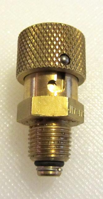
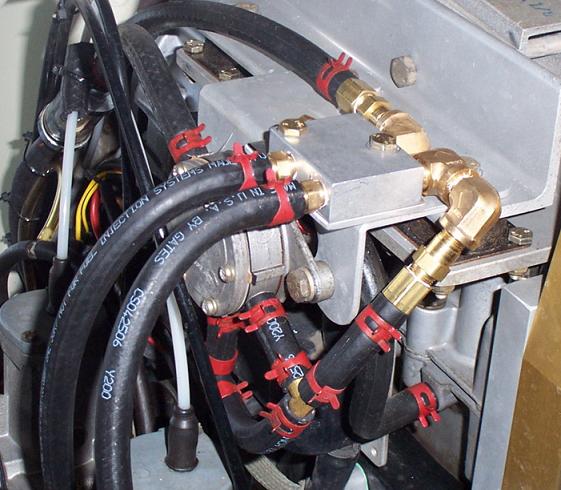
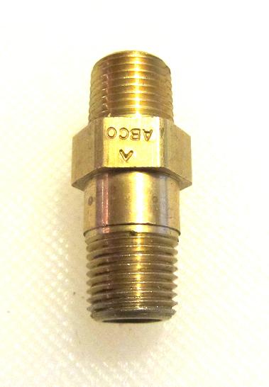
The solution to this problem is check valves. A check valve needs to be installed after each pump to prevent back flow. A check valve in this application must be resistant to alcohol and gasoline and have a very low crack pressure. While the check valve could be installed in various locations, the closer to the carb it is, the better. Only what is behind the check valve is protected by it. This is why I designed a system with a manifold block near the carbs with check valves at both inlets, and the manifold outlets to the carbs. The only parts of the system that are not redundant are the lines between the manifold and the carbs, which are about 12 inches in length. No single failure in this system, short of an empty tank, could fail both systems. I highly recommend this system for true redundancy, and sell this system on my website, or you can buy individual components of it.
Fuel Quality
The last consideration of the fuel delivery system is the fuel itself. Probably the most debated factor of this topic is what fuel to use. Some people are in the avgas-only camp, others insist than non-alcohol pure gas is the answer, yet others simply burn the cheapest pump gas they can find.
While there is no doubt that avgas has the strictest quality and consistency of any fuel available, it is costly, sometimes hard to obtain, and has a high amount of lead. Pure gas is a great solution, but can be harder to find than hen’s teeth. Every batch should be tested to insure it is alcohol-free.
A method of testing for alcohol can
be found at:
http://www.challengers101.com/AlcoholTest.html
And yet many folks simply run the cheapest junk E-gas at the local filing station. Officially, Rotax has stated that up to 10% ethanol in fuel poses no threat of engine damage. I suspect that would pretty much apply to any engine provided the soft parts in the fuel system are resistant to it, and anything made in the last 15 years certainly should be.
In my opinion, I would categorize pure gas as the best option if it is truly available in your area. Avgas is a very close second. It’s only disadvantages being its lead content, availability and price. But I do not hesitate to run E-gas with a couple precautions.
First, do not run E-gas in very cold weather. That is
because E-gas absorbs moisture. If it gets cold enough, it will eventually
crystallize and can plug up fuel filters and pickup lines. Furthermore, there
are over 140 different recipes for gasoline in the
Another serious consideration for E-gas is that it does not store nearly as long as the other types of gas. If mixed with oil and stored in a poly tank it will deteriorate even faster. Exposure to sunlight in a poly tank also accelerates the deterioration of E-gas. If you use E-gas, use it in warm weather and try not to leave it in the tank for long. If it has sat for more than a month or so it’s probably best to drain it and run it in a lawnmower or some other ground-bound machine.
One last issue with E-gas that I have run into is that it does not play well with capacitance type fuel sending units and can begin to give erroneous readings. A float type sender will solve this problem.
This article has endeavored to present an overall picture of the many considerations that should go into the design of a fuel delivery system. When the design brings together the right mix of components it will serve you well. Happy and safe flying will be yours to enjoy without the worry of fuel delivery engine out issues.