Fuse Box & Power
To Instrument Panel


We will be presenting two ways to set up and/or create an electrical panel fuse box for all your wiring interconnection needs. The first solution uses the Kuntzleman Electronics Hot Box, available from Kuntzleman Electronics, Inc.. While it is the simplest and recommended solution, it is also a more expensive way to accomplish this than the second solution.

The second way is a lower cost solution by building your own electrical fuse, interconnect panel and is much easier to do then you would think.


Kuntzleman Electronics Hot Box

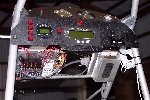
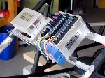
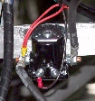
Our builder has opted to use a Kuntzleman Electronics Hot Box for his electrical wiring fuse box. This is the simplest way for an interconnect to all the electrical wiring for your Challenger. The hot box provides all the +12v connections you will need for the interconnections to wire your gauges, instruments and other items, such as a landing light. The builder has attached a Key West regulator to the end of the hot box, but removed the regulater later and moved it to the engine area of the fuselage.

Just run the hot, or red wire from your instruments to the +12v terminal block and the ground or black wire from your instruments to the ground terminal block. Kuntzleman provides a hot box schematic which will tell you where to attach your instrument wires.
         
Click to Enlarge


Click to Enlarge
         

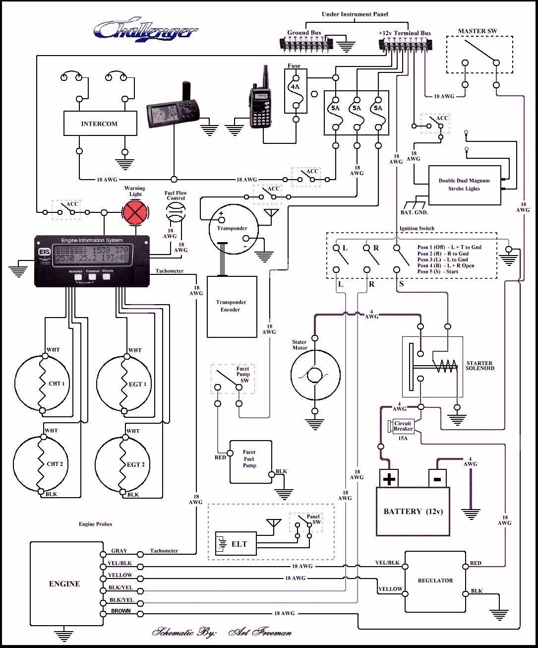
The main +12v power lead to the hot box will run from the "large", left terminal of the starter solenoid to the "Master Switch" on the instrument panel, then to the main +12v power terminal on the hot box. That's all there is to adding a fuse and interconnect panel to your plane. "SIMPLE"!

The wiring schematic to the right can be used to show you the wiring connections for instrument wiring.

         
Click to Enlarge


Build It Youself Wiring Fuse Panel

Materials Needed:

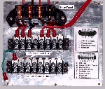
  1. The base of the fuse and terminal panel is a 6"x6" piece of aluminum sheeting salvaged from the end piece of the outboard wing end sheeting. 18 gauge wire was used for all connections.

  2. The black fuse buss (top) was purchased at Auto Zone for under $5. In this case, the builder only needed three fuses active, but wired all four fuse terminals for possible future accessory addition. All that would be needed would be to insert the correct fuse rating for the added accessory and wire the accessory to the fuse lead (hot) and ground terminal block.

  3. The +12v and ground terminal blocks under the fuse block were purchased at Radio Shack for under $10. Each power terminal block has a linking power terminal strip on the top of the terminal block connecting all terminals together on each block. This will allow for every terminal on the blocks to be either hot for the +12v power block or grounded for the -12 or ground terminal block.


Click to Enlarge


Click to Enlarge
         

Basic wiring for the fuse and terminal block:

  1. Wire the +12v power lead from the Master Switch on the instrument panel to an end terminal of the +12v power buss. This will make the +12v buss hot or hold a +12v DC voltage when the Master Switch is turned on. The first photo to "left" was before it was installend in plane.

  2. Each 5 amp fuse is wired from the +12v terminal block to the individual fuse terminal. The fuse output terminal is then wired to the instrument or accessory you want to power. Thus, each instrument or accessory has an in-line fuse protecting that instrument or accessory.

  3. The ground terminal block or ground buss is wired to and bolted to the Challenger frame to create the best ground. This way, you are able to remove and clean the connection later if needed.

  4. Any instrument or accessory that already has an in-line fuse can be wired directly to the +12v and ground terminal busses without being wired to the panel fuses. For example, most aircraft NAV/COM radios will have a built-in fuse.

  5. It is good practice to label your fuse buss and terminal busses for later reference as where each instrument or accessory was wired. (See top, left photo)


Click to Enlarge
         

The main +12v power lead to the fuse panel will run from the "large", left terminal of the starter solenoid to the "Master Switch" on the instrument panel. Then from the master switch to the fuse panel +12v terminal buss. That's all there is to adding a fuse and interconnect panel to your plane.

The wiring schematic to the right can be used to show you the wiring connections for instrument wiring.

         
Click to Enlarge