
Your hardware may vary.
5 ea. Short bolts or screws5 ea. Flat or lock washers
2 ea. Long bolts
1 ea. Metal mounting flange
1 ea. Rubber gasket ring
Installing A Capacitance Tube Fuel Gauge Into The Fuel Tank
AUTHOR The following installation information has been provided by Mr. Mike Harrison of "Skyes the Limit". This is from Mr. Harrison's installation instructions shipped with the Capacitance Tube Fuel Gauge.
What Is A Capacitance Tube Fuel Gauge? Well, the inner rod and outer tube form the two plates of a capacitor with the little discs inside being the separators for them. With no fuel up inside the "capacitor" it has a given value of capacitance. As fuel is added to the tank and it goes up inside the tube assembly, the capacitance changes. Auto and aviation fuel evidently cause a small difference in capacitance for a given level. Hence, the difference in the gauge reading between the two fuels.
|
Your hardware may vary. 5 ea. Short bolts or screws5 ea. Flat or lock washers 2 ea. Long bolts 1 ea. Metal mounting flange 1 ea. Rubber gasket ring |
 |
Place sender ring over flat area of tank and mark the center of the ring. Drill Įö hole at the centered location. |
 |
 |
Place rubber gasket ring on sender as shown with screws to hold gasket on sender. Place sender in tank and measure the distance from the top of tank to the bottom of the rubber gasket. Add 1/4 inch to this measurement to obtain the total length of tubing to be cut off in the next step. Measure a distance from the bottom of the sender equal to the measurement obtained previously, with the 1/4" added. Mark the tube and cut with a tube cutter. |
 |
 |
Carefully de-bur the outer tubing and push one of the small plastic spacers up into the end of the outside tubing. (This keeps the inner wire from touching the side of the tubing.) Cut the end of the inner wire flush with the face of the outer tubing. It is okay if the end of the inner wire is closed off when cutting. |
 |
Place the sender in the Įö hole exactly as it will be for the final installation. Drill the 5 mounting holes into the tank using the sender holes as a guide. Note: Place a screw in each hole after drilling just to keep the sender from moving around while drilling other holes. When finished, remove the sender unit. De-burr the drilled holes for a clean installation. |
 |
 |
Use a file or grinder to modify the metal flange so that it looks identical to the one finished in the picture below. Picture should be to scale for matching yours to the finished shape. This step allows a much smaller slot in top of tank for better sealing of the sender. Flange is pictured with the flat side down. |
 |
Take a measurement of your modified flange in order to determine how long to cut the notch in the top of the fuel tank. Carefully notch the tank exactly as pictured. The notch will be 1/8ö wide, as long as your measurement from above, and will start at the pre-drilled hole as shown. After notching tank, clean tank thoroughly with compressed air or a vacuum. Use goggles! |
 |
 |
Loop a piece of safety wire through the screw hole on sender flange exactly as shown below. While holding safety wire firmly, slide the sender flange into the notched slot of the tank. Don't let go of that safety wire!!!! |
 |
 |
Slide the safety wire to the side of the notch in the tank and pull up on the safety wire. This brings the flange up flush to the tank and allows for easy alignment of tank and flange holes. While holding the flange flush, temporarily install two of the small screws as shown. Now it is safe to remove the safety wire! |
 |
 |
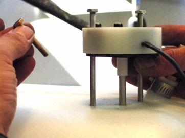
Place the sender in the tank with the rubber gasket on the bottom and align for final installation. Install 2 of the long bolts through the sender into the metal flange as pictured. Now remove the two small bolts that were temporarily installed into the flange. |
 |
 |
Hold the long bolts up and push the sender unit flush with the surface of the tank. Install 3 of the short screws with their lock washers through the sender holes and into the flange. Now remove the two large bolts and install the remaining two small screws and lock washers in their place. You have now completed the Fuel Sender Installation. |
 |
The wiring of this gauge will be covered on the "Electrical Wiring" web page when it is created.
Please return to the Featured Build Menu by clicking on your browser's "BACK BUTTON".