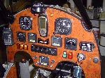
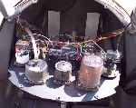
Instrument Panel Design & Layout
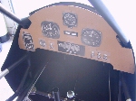
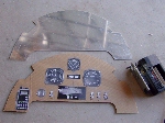
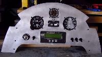
The instrument panel design shown on this page is only one out of dozens of possibilities. Not only are there many different designs, but panel materials, individual instruments, analog instruments and digital instruments. The possibilities are endless, so don't take this design as the only choice you will have.
Note: Instrument panels are normally laid out with the flight instruments on the top row of the panel with the engine instruments on the bottom row. This helps if you transition from one plane to another. Example of top row instruments would be; ASI, ALT, VSI, in that order. However, our builder decided to reverse this order out of personal preference.
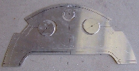
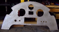
You should now have something like this. The blank instrument panel should match the perimeter of your template. |
Layout Of Instruments
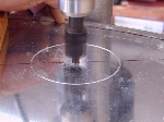
Now it is time to lay out how the instruments will be placed into the panel. First, sketch your intended layout out on the cardboard template before marking the panel. When satisfied with the layout, carefully measure and mark the panel with a fine line felt marking pen.
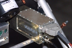
In most cases, installing an instrument brace or support will not be necessary. However, if you install a somewhat long instrument, like a transponder, you may wish to install under instrument bracing. |
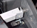
It also recommended to place a piece of rubber padding between the transponder or other such instrument and the aluminum tube brace to help absorb any shock. In addition to this, tie wrapping the instrument to the tube brace is also recommended. |
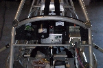
NOTE: The bracing at an angle, just above the rudder peddles will be described on the electrical wiring web page as this brace was placed there to attach the hot box and Key West regulator. |
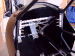
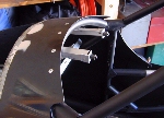
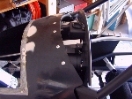
If the panel was attached directly to the FWF tube at the top, then the bottom of the panel would require some type of standoff's to attach the panel to the FB-1 tubes. In the case of an angled or bent panel, like Mike Harrison's (Below), the panel would be attached to the FWF & FB-1 tubes without any standoff's being required. |
Before you can install your instrument panel permanently, you will need to wire all of the gauges to the rear and attach any tubing, like the pitot tube to your airspeed gauge or EIS unit. One way to get around this problem is to permanently mount your fiberglass nose cone "AFTER" you have installed the instrument panel and wiring. In doing so, this will give you all the room you will need for wiring the gauges. If you are using the factory chisel nose, you will not have to worry as the nose will not be covered until you are ready to cover the fuselage. Another option is to place your instrument panel on hinges with a couple of screw key locks so you can tilt your panel out to work on it or to use "ALL" screw key locks so the panel can be easily removed at a later date. |
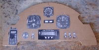
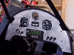
Here is a very nice and somewhat large instrument panel, submitted by: Jacques Lajeunesse in Québec City, Canada. |
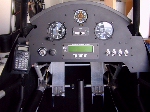
Here is a very nice and slightly larger instrument panel on a hinge arrangement to allow easy access to the back of the panel, submitted by: Ralph Shultz. |
Please return to the Featured Build Menu by clicking on your browser's "BACK BUTTON".