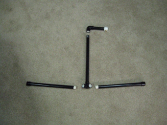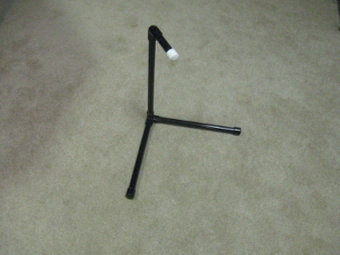
Figure 1. The Balancer
Do-it-Yourself $5 Prop Balancer
By: Ralph Shultz
Figure 1. The Balancer |
When faced with repairing or applying a new coat of varnish to your prop you will also be faced with checking the balance of that prop. Everyone knows that a prop which is out of balance, will not run smoothly and may track poorly at operating speeds. You have probably heard statements like “A prop must be balanced to within a fraction of an ounce”, and wondered what that really means. The question then arises “How does one go about balancing a prop?” An Internet search on the subject will turn up several different types of prop balancers. Some look complicated, while others look too simple to actually do the job. Some of these are commercially available and some can be made at home. Most tend to be pricey, hard to fabricate, leave much to be desired, or appear to be not quite up to the job. Well worry not… because for just a couple hours effort and by using just a few dollars worth of materials you can build a balancer that will do the job just fine. The balancer described below can be constructed by you and it will balance a prop to a within a cat’s whisker in two planes. First it will balance a prop radially (think blades of equal weight) and secondly, axially (think top vs bottom when the prop is mounted and stopped in the horizontal position). Additionally, with this inexpensive balancer the balance indicator can also be adjusted for sensitivity to boot! This balancer consists of two main components: a stand and the balance indicator which is the important part of the design. The indicator will show you the directional location of any unbalance and how well the prop is balanced. This design borrows ideas and concepts from a couple of homebuilt designs. Its operation takes advantage of gravity to perform its primary balance function. This tool is about as simple as it gets, but make no mistake … it will do the job! Materials needed for the stand:
The stand itself is straightforward. A look at Figures 2 & 3 should answer any questions one might have as to how to cut and fit the pieces. I like to glue all the caps on to the PVC pipe. I also glue the elbow to the 6-inch long pipe and end cap with the threaded hook. The threaded riser is tightly threaded into the 3-way connector. I leave all other joints unglued to facilitate breakdown and storage. Painting the finished stand in black makes it look more professional.
Materials needed for the balance indicator:
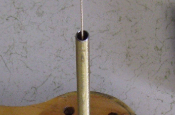
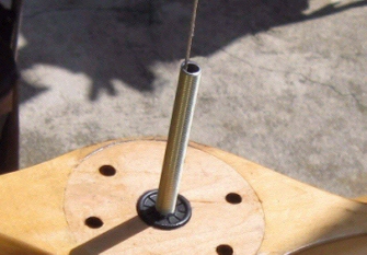
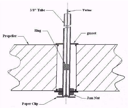
See Figure 6 it is a cross-sectional view.
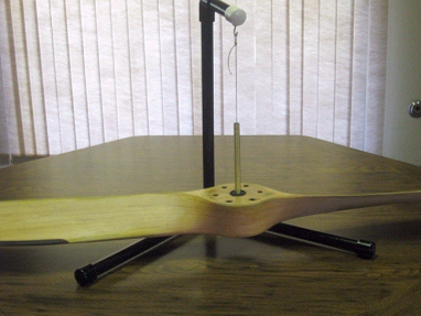
The balance indicator is a simple design with a few features borrowed from a design by Jeff Jeter. It works on the principle that a balanced prop hung horizontally and supported at its center of gravity (CG) will assume an absolutely horizontal attitude, that is to say “it will be square with the world”. The challenge is how to hold the prop at its CG. The prop’s CG should be at the exact center of the prop, radially at exactly the center of the prop hub, and axially halfway through the thickness of the hub. The balancer allows the user to set the point at which gravity’s pull on the prop is resolved out of the prop and into the supporting twine, assuming that half-way through the prop hub and along the axis of the center hole of the prop is the correct spot of the CG. Moving the pliable slug up or down inside the 3/8 tubing, relative to this center position in the prop, the balance indicator can be made more or less sensitive to register any out of balance condition. Moving the slug up renders the balance less sensitive and down more sensitive. Think of trying to balance an upright dowel in the palm of your hand vs. holding it loosely at the top with your fingers. The slug can slide on the twine and be moved up or down inside the 3/8” tube. Inserting a small diameter dowel from the top or bottom can accomplish this. I use a bamboo skewer, but anything that fits will do the job. The state of a props balance or unbalance is indicated by the relative position of the twine at the top of the 3/8” tube and it’s inside diameter. A perfectly centered position of the twine is of course what one wants but that really is not required. If the string is not centered in the tube the user can judge the amount of any out of balance condition that exists in the prop by taking one or more 1/4 sheet(s) of 20 lb. printer paper and draping the paper over the tip of the props high blade(s). This should tend to draw the string into the center position of the tube. Notice how much the twine moves in the tube. The direction it moves points to the light blade(s), this is where more weight needs to be added to the prop or perhaps removed from the heavier blade(s). By experimenting with paper weights in this manner the user can quickly tell how close the prop is to being in perfect balance (Figure 4) or whether it is out of balance (Figure 5). If the twine touches or bends at the tube's edge the out of balance condition of the prop may be much more than if it hung mid-way between tube's inner edge and the center datum line of the tube. The visual reference and the weight of paper added could be helpful in determining how much weight must be added or removed to bring the prop into an acceptable balance condition. See Appendix A for how to do this calculation.
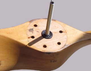
I weighed a 1/4 sheet of 20 lb. printer paper on an ammunition reloading powder scale. The scale registered 19.5 grains (7,000 grains = 1 lb.). If that paper was to be draped over the tip of a 60’ diameter prop (30” radius) and the twine moved off the centered position in the 3/8” tube but not touching the tube side that would be equivalent to 1.337 inch-ounces of unbalance (30 x (19.5/7000) x 16). Put another way; if it takes a 1/4 sheet to bring the twine to a centered position then the imbalance would be 1.337 inch-ounces. I have no idea as to what an unacceptable out of balance condition would be. What I can tell you is that a prop I dinged, repaired, re-varnished and balanced ran true and without vibration all the way up to an engine speed of 6500 RPM. On balancing my repaired prop the twine was very nearly but not perfectly centered and the effect of a single "paper weight" placed on the prop's tip could easily be seen. When removal of weight from a blade is required in the process of balancing a prop never remove material from the bottom surface or the leading and/or trailing edges. Material removed from these surfaces is more likely to alter the prop's airfoil angle of attack and thereby its lift, drag and thrust characteristics... more so than if the weight were removed from the top surface. Should it be necessary to remove weight from a blade do it along the top surface in the area of max thickness and try to maintain the same curve. Axial balance can be achieved by adding coins (stacked if necessary) along the outside edge of the prop hub aligned radially between the mounting bolt holes if possible until balance is achieved. These coins are then weighed and an equal amount of lead weight (fishing line weights work great) are matched and set aside. A hole is then drilled under the coins and the lead weight inserted and glued in place. Material from the drilled hole is then mixed with a little glue and filled in the hole above the lead weight. All this is done prior to adding the finish varnish coat to the prop. Final touches to the props balance are usually obtained by applying more varnish to the lighter blade(s). By applying varnish to appropriate areas of the prop, in multiple coats if necessary, one can “walk in” its balance quite nicely. Figures 6 & 7 depict parts of the balance indicator.
A few final notes:
The key to this balancer is the internal slug and its placement. It should fit snugly inside the 3/8” tube. How the tube is centered and held in the prop’s bore is not all that important. Remember … there are many ways to skin a cat! Just take care that the tube is centered in the bore and be sure to check that it is perpendicular to the prop’s plane of rotation (hub face surface). Check this in two directions, 90 degrees apart, as this is very important! The balance is sensitive to air currents and your balancing efforts should take place in a sheltered area or indoors. More information on prop repair and re-balancing can be found at: Wood Prop Repair & Balancing Well there you have it! A $5 prop balancer you can build yourself. I believe you will enjoy building this prop balancer and using it. Having it ready in your specialty tool kit when needed is nice, as well. This project will return to you a good measure of personal satisfaction! Additionally, it can help keep your Challenger or other sport-type airplane props purring nicely. |
Appendix A: The weight of the paper weight(s) can be used in place of the coin weights to calculate the weight needed at the prop hub (which will be deposited into a drilled hole). That calculation looks like:
|
Using the values mentioned in the article we get:
|