Radio and Intercom System Install


A word of sound advice. There are "SOME" pilots and builders out there who have decided to save money by not buying and installing a radio system in their plane. This in itself is a "DANGEROUS" decision for more reasons than I would care to list. However, the most important reason for a radio system is during take off and landing procedures. Many small uncontrolled airports do have... fairly moderate pattern traffic at times. Without a radio to announce your intentions and to hear other aircraft, you may place yourself, your passenger, and those in other aircraft operating near you in "Harm's Way". The extreme danger of being injured, or worse... killed in a ground or mid-air collision is increased without stating your intentions or hearing those of other aircraft operating or flying in your close proximity. A working radio is a good way to help ensure aircraft separation and safety.

Many aircraft radios offer more than just a two-way communication capability. They usually offer other features such as: quick buttons to jump from current channel to another channel, lighting variations from a short duration to a full-time ON, weather condition channels, and other important features. Know your radio so you can operate it quickly and efficiently.

There are many radio and intercom systems on the market to select from. Therefore, we have chosen the I-Com radio and the Comtronics, Dual-Com II intercom for this installation. One thing you can be sure of, and that is, installing a radio and intercom system is very simple. Those of you with a Challenger I may ignore the information of installing an intercom.


Basic Radio System Layout

For Challenger II
Click to Enlarge
         

The drawing to the left shows a radio system with intercom for two people in a Challenger II or similar aircraft with dual seats.

To the right, the diagram is for a Challenger I or single pilot aircraft radio system without intercom.

         
For Challenger I
Click to Enlarge

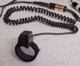
A "coil patch cord", such as shown on the right, is used in a Challenger I, single place to connect the headset and PTT buton to the radio.

         
For Challenger I
Click to Enlarge

Mounting The Intercom Controller

For Challenger II
Click to Enlarge
         

The following installation is to mount the Intercom Controller on the front side of the front seat down tubes. However, for a taller pilot, it would be far better to install the controller on the rear side of the down tubes.

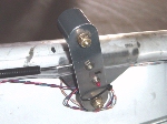
Using a piece of scrap aluminum sheeting, measure, cut and rivet the aluminum plate to the front seat down tubes.

By opening the intercom casing, you can drill through the intercom back panel and aluminum sheeting to mount and rivet the intercom controller to the sheeting. This location is suitable for ease of adjusting the volume controls by either pilot or passenger.

         
For Challenger II
Click to Enlarge


For Challenger II
Click to Enlarge
         

A Comtronics, Dual-Com II intercom is being installed. The front of the intercom is the volume control buttons (outside) for the headsets. Next is the connector receptacle for plugging your headsets into the intercom. The toggle switch (center) is used to toggle between two radios, if you use two.

On the back, looking bottom to top, we can see the power (black & red) wire. Next is a mini-jack for music input, like from a CD player. Then we see the PTT button (Push To Talk). Finally we see Radio #1 and Radio #2 inputs.

         
For Challenger II
Click to Enlarge

Other locations for the intercom controller would be under the front seat, and facing forward to allow the pilot to adjust the volume controls, as well as, the ON/OFF button. A right-hand, side mounting also offers decent ease of adjustment to the unit's control panel by the pilot. However, both locations make it cumbersome to adjust the intercom controls, as well as, dealing with the rear headset cord in these locations.


Most Common Antenna Types
         

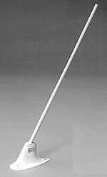
A standard 18 inch aircraft rod type antenna is show on the left. About 118-136 MHz. Wt. 8 oz. BNC termination. It is supplied with weather sealing rubber pad and mounting hardware. This type of antenna is usually mounted on the crown of the front gap cover for optimum performance.


Older Version

Current Version
         

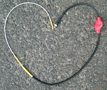
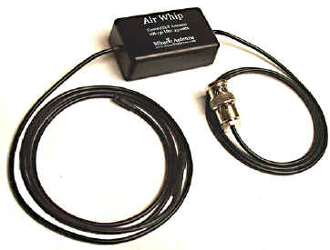
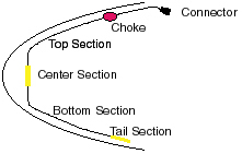
In the left photo is shown the popular Miracle Air Whip Antenna. Installation of the Miracle Air Whip Antenna is a snap. It is designed to be attached to the inside of the fiberglass nose. You can use hot glue, silicone or duct tape to install it. The Miracle Air Whip is a full half-wave dipole antenna which allows it to be pre-tuned for maximum radiation during its manufacturing process. It operates completely independent of ground planes or wires. It is also a lower cost alternative to the standard communications antenna like the one mentioned above.


Also, see Build Your Own Comm Antenna on our web site.


Possible PTT (Push To Talk) Button Locations

Click to Enlarge
         

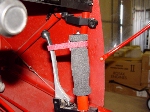
The PTT (Push To Talk) button can be mounted in several different locations as can be seen here. The photo to the left shows the PTT button mounted in the factory issued front throttle quadrant handle.

The photo to the right shows the PTT button mounted in the top of the front control stick.

         
Click to Enlarge

In this example, the PTT button is a much larger, rectangular button than the others and uses Velcro to attach it to the forward down tube.


Radio Placement and Connections

Click to Enlarge
         

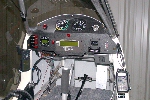
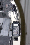
Generally speaking, for the Challenger or any similar type of aircraft construction, the radio is usually mounted close to, on or in the instrument panel. This allows the pilot easy access to its controls. The design of the radio bracket you will need to fabricate will depend on the radio model selected and its particular mounting system.

Run your patch cord from the intercom controller down the seat back down tube, inside or outside the downtube, along and below the side rail to the instrument panel location of the radio. The coax antenna cable will be run from your antenna to the radio location. Its routing can vary depending on the antenna's location. Lastly, you need to run and connect the power lead (Red Wire) from the radio to your fuse panel's +12v power bus and also connect its ground (Black Wire) to the ground bus.

         
Click to Enlarge

The Challenger I headset and PTT button connection will use the "coil patch cord" shown above under "Basic Radio System Layout" instead of the intercom patch cord.

That's it!... u are done! EASY!!!!