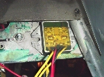
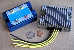
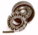
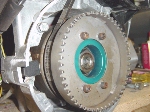
The charging system of the Rotax 503 is a 12 pole, flywheel generating system. The FAA refers to it as a lighting coil instead of an engine driven alternator. It's located on the magneto or starter end of the engine and consists of 12 integrated permanent magnets built like a flat "cup" and mounted on the crankshaft.
The other four coils are used for the ignition system, two for each system on a dual ignition setup. This gives the system it's independency for each ignition system. They are called the "charging coils" even though they have nothing to do with charging the battery. The output of these coils consist of two pairs of wires. In each pair, one is white and the other is green. The white wires connect to each other and to ground inside the unit. The gray wire is an output used with a tachometer. The brown wire is simply a connection to the metal frame of the assembly, a "ground" wire.
A wiring diagram of the alternator is shown at right. The output of the eight coils is 170 watts AC (alternating current) at 6000 RPM, according to Rotax, which is about 12 to 12-1/2 amps of current at full output. Since it's output is AC like a car's alternator, a rectifier must be used to change the AC to DC (direct current) for battery charging, running radios, GPS's, strobe lights, etc. Typical unregulated AC voltage readings are: 16 volts (VAC) at 1300 RPM, 27 VAC at 2200 RPM, 50 VAC at 4000 RPM, and 77 VAC at 6400 RPM. |
 |
As you can see, some way to keep the voltage at a nominal 13.8 VDC is needed. Enter our voltage regulator which takes the DC voltage from the rectifier and regulates it to approximately 13.8 VDC. An automotive alternator uses a field winding to generate the magnetic field which causes the stator to produce the electricity. This field winding is fed from the voltage regulator and creates a magnetic field to induce voltage in it's stator windings. The regulator senses the battery's voltage and, by varying the voltage to the field winding, varies the magnetic field which in turn, varies the output voltage of the alternator. Since we have permanent magnets generating a constant magnetic field for the Rotax stator windings, an automotive type of regulator cannot be used.
What Rotax uses is typical of many motorcycle regulators. It's called a shunt regulator since it momentarily shorts (or shunts) the output of the stator to ground whenever the voltage rises above a particular factory-set voltage, thereby keeping the system voltage constant. As the load on the lighting coil increases, such as turning on lights, radios, auxillary fuel pumps, or charging a battery, the regulator has to shunt less voltage to ground because the various loads use the excess power. Rotax calls these loads "consumers".
In lightly loaded situations such as a fully charged battery and no electrical equipment turned on, the power draw can be as little as 15 watts or just over an amp of current. In this case, the regulator is shunting a lot of excess power to ground which keeps the voltage at a nominal output of approximately 13.8 VDC. It's a very power-wasteful regulating system but is simple and usually works rather troublefree if set up correctly.
TROUBLESHOOTING THE CHARGING SYSTEM
(You may wish to refer to the wiring diagrams at the end of this article to get an overview of the complete electrical system.)
Occasionally, there may be a problem develop in which the battery won't charge at all or, the charging voltage is either too high or too low. If the battery is known to be good, it's time to check the charging system. The wire connections should be checked first to make sure they are not only tight, but free of corrosion. Corroded or loose connections will prevent a proper charging voltage from reaching the battery.
Another check to be made is the correct battery voltage. Without the engine running, a healthy battery should show about 12.6 to 12.7 VDC. With it running, that should be up around 13.5 VDC to as high as 14.5 VDC which indicates the lighting coil/rectifier/regulator system is working. A voltage of 13.8 is ideal as it gives a good charge rate without causing the battery to gas. Lead-acid batteries begin to gas about 13.9 VDC.
If the voltmeter reads higher than about 14.5 VDC, replacement of the regulator is recommended since higher voltages will boil the battery and cause water to be needed much more often, not to mention the possible damage to electronics from too high an operating voltage.
If the meter only indicates the battery voltage with the engine running, connect the voltmeter to the yellow output wires and set the meter to read AC. Run the engine and see if the voltage varies with engine speed and according to the values previously given (which are not absolute). If it does, the lighting coil is probably okay. Since the rectifier/regulator is a combined unit and is getting it's required input from the lighting coil, it should be replaced and the voltage check repeated for the battery. This check should now be good and the problem solved.
If the lighting coil (or stator) output isn't what it should be, then it should be checked for shorted windings or other problems and will probably have to be replaced.
Wiring Diagrams from Rotax
This section consists of six wiring diagrams taken from the Rotax manual that show how a given voltage regulator is wired into a given electrical system.
Circuits for two different regulators are shown: # 264 870 and # 866 080.
Note that the 866 080 regulator requires a minimum current load of one amp in order to prevent excessive AC voltages from being applied to the regulator input. The 264 870 regulator does not require a minimum current load.
For each of these regulators, wiring diagrams are given for:
- An electrical system that does not use a battery.
- An electrical system that includes a battery.
- An electrical system that includes an electric starter.
A word of explanation: Because the same alternator is used to provide electrical power to each of the circuits, and because the wiring diagram of the alternator assembly is shown above, that part of the wiring diagrams has been removed. This permits the remainder of the diagram to be enlarged to provide greater clarity.
In all the following diagrams, the yellow and yellow/black wires of the "lighting coils" connect to the yellow, AC input wires of the regulator.
Regulator # 264 870 No battery.
This circuit is quite simple. However, note that the case of the regulator is the negative DC output, and the positive DC output wire is BLACK, not red as you would expect. Rotax refers to the components or devices that draw current as "consumers." In this circuit, all such devices may be switched OFF without affecting the regulator. Further, note that a capacitor is connected between the DC output of the regulator and ground. This capacitor is essential for "smoothing" the output voltage of the regulator if that output is to be used for devices like a radio, a Hobbs meter, or a GPS unit. The capacitance of the capacitor should be at least 2,000 microfarads with a voltage rating of at least 25 V. And observe that the capacitor is polarized. If you reverse the positive and negative leads of the capacitor, it will likely blow up in short order. |
 |
Regulator # 866 080 No battery.
 |
This circuit is similar to the one above with the following exceptions. First, the case of the regulator is not electrically active. Instead, a black wire provides the ground connection. And observe that the output wire is RED. This circuit also requires the capacitor for smoothing the voltage. The load (consumer) is shown as consisting of two parts. One part may be switched ON or OFF, but the other part must be permanently connected to provide the minimum one amp current load at all times. |
Regulator # 264 870 With battery. Circuits that have a battery do not require the capacitor. Because this regulator does not require a minimum current load, all the load devices (consumers) may be switched ON or OFF. Note the 16-amp fuse in series with the black output wire of the regulator. |
 |
 |
Regulator # 866 080 With battery. This circuit is almost identical to the one above except part of the load is unswitched. This is the part that provides a minimum current load of one amp for the regulator. |
Regulator # 264 870 With battery and electric start.
At first glance, this circuit appears rather complicated but it really is not all that much more so than the others. The only thing added is the starter circuit.
First of all, the terminals of the solenoid, B and M, are the posts to which the big battery cables connect. These are shown as extra bold in the diagram. You can trace them from the positive terminal of the battery to the starter. The solenoid serves as the "switch" for this circuit.
The solenoid-coil circuit includes a fuse and a normally-open push-button switch for the starter button. Although a value is not specified for the fuse, a 5 amp fuse should be more than adequate. When the starter button is pushed, current flows from the positive terminal of the battery through the fuse, then through the coil of the solenoid, and then through the starter-button switch to ground. In all these circuits, all the grounds are assumed to be connected to the negative terminal of the battery. It is good practice to run wires for the grounds as opposed to using the metal frame of the aircraft as a ground conductor. Using the frame as a ground almost always causes problems; it's just a matter of time. And obviously, a heavy "battery cable" must connect from the engine to the battery negative to complete the circuit for the starter. |
 |
All consumer devices may be switched in this circuit. There is no minimum current requirement for this regulator.
 |
Regulator # 866 080 With battery and electric start. This circuit is almost identical to the previous one. The only thing that is different is that a part of the load is unswitched so that the minimum current load of one amp is always present for the regulator. |
These photos are three regulators commonly used with our planes.
 Click to enlarge. |
 Click to enlarge. |
Jim Hayward & Doc Green

