Adjusting Aileron & Rudder
Turnbuckles and Cables


As a preliminary comment, a Left and Right directional reference should be noted when working on your Challenger for this article. In most articles, this would not be necessary, but here it would be important to review and establish a directional reference first.

When referring to left or right, the reference will always assume you are in the seat, facing forward. In which case, to your right would be the right wing on the plane and to your left would be the left wing. This will become very important in the following discussion on adjusting the aileron and rudder cable tension.


Aileron Cable Adjustments

The following procedure can either be done early in the build or at the end during final assembly. Challenger I builders can disregard information concerning the rear turnbuckle and cable adjustments.


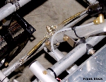
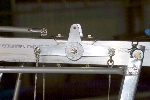
Turnbuckles, As Seen Coming From The Factory

Click to Enlarge
         

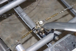
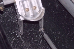
In the two photos to the left (front) and right (rear), you will see the aileron cables attached to the turnbuckles, then to shackles, and finally to the retaining bolt on the control stick. This is set as a starting place by QCU and is not adjusted for proper centering and tension of the control stick and ailerons.

         
Click to Enlarge

Aileron Bellcrank

Click to Enlarge
         

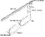
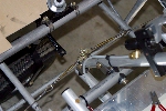
The photo on the left shows the aileron bellcrank. The drawing on the right shows how the cables are connected from the control stick turnbuckles to the aileron bellcrank.

Rule of thumb: When the cables are adjusted correctly and if the control stick is centered, the aileron bellcrank will be perfectly level horizontally with the root tube, as shown in photo to left.

         
Drawing of Aileron Mixer Arm
& CAble Assembly

Click to Enlarge

Adjusting Turnbuckles For Aileron Cables

You will first need to center the front control stick before adjusting the front turnbuckles. Adjustment of the turnbuckles can be performed by turning the center portion of the turnbuckle either left or right to tighten or loosen the cables.

  1. With the front control stick centered, adjust the aileron cables with the turnbuckles until the aileron bellcrank is horizontally level with the root tube. When this is done, you may notice the rear stick will either be a little to the left or right of center. Don't worry about that now.

  2. When adjusting the cables, do not over tighten them as this will cause excessive wear on the pulleys and may fray the cables. You should adjust the cables until just snug so that when flicking the cable with your finger, it makes a nice "THUMP" sound. If flicking the cable makes a twang sound like a guitar string, the cables are too tight, so loosen them back up.

  3. Do the front aileron cable adjustments first, then you can adjust the rear control stick aileron cables to center the stick.

  4. Alternating from left to right turnbuckles, evenly take the slack out of the aileron cables. DO NOT place the safety wire on the turnbuckles at this time as further adjustments may need to be done later.

  5. Repeat steps 2 through 4 above for the rear aileron cable adjustments to bring the rear stick to the center position. If this cannot be done due to maxing out the turnbuckle, you may need to readjust the front stick turnbuckles to allow for more travel to the rear control stick turnbuckles.

  6. When both of the front and rear aileron cable adjustments are finished with the control sticks centered and both sides of the aileron bellcrank are straight with the root tube, install a "TEMPORARY" piece of .030" safety wire in the turnbuckles to hold them in place for now. The reason for this will be clear when you have your plane almost finished with the wings on and you are ready to adjust the ailerons. The aileron push rod can only be adjusted "SLIGHTLY" at the ball joints and further cable adjustments "may" be required.

    When all has been fully adjusted, ailerons, aileron cables and so on, you will then be ready to permanently install the safety wire in and on the turnbuckles.
    (Refer to following safety wire wrap instructions at bottom of page, taken from the Challenger build manual.)


Turnbuckle And Cable Adjustment Completion

Click to Enlarge
         

The photos on the left and on the right show how the turnbuckles will look when you are completely finished.

         
Click to Enlarge


Rudder Cables And Pushrods

It is recommended to assemble and install the rudder pedal interconnect pushrod assembly early in the build. However, the rudder cable and turnbuckle adjustments can "ONLY" be done during final assembly after the rudder and rudder horns have been permanently installed.


Rudder Pedal Interconnect Pushrod Assembly

Before you can start adjusting the rudder cables, you will first need to construct the rudder pedal interconnect pushrod for each side rudder pedals.

NOTE: Challenger I owners can skip the rudder pedal interconnect pushrod section.

         
Click to Enlarge


Click to Enlarge


Click to Enlarge


Click to Enlarge
         

To determine the length of your rudder pedal interconnect pushrods, place both the front and rear seat rudder pedals about mid-point of full travel to the front and back. Now, slip the aluminum pushrod tubes together as well as placing the clevis forks into each end of the assembly. Telescope the pushrod tubes as needed to "TEMPORARILY" insert the clevis pins into the rudder pedal horns, front and rear. (NOTE: Use the outboard front pedal horn for the interconnect pushrods. The inboard horns are for the front wheel fork pushrods.) Check to make sure the front and rear pedals are centered from full pedal travel. Now, slide the center (larger) aluminum tube to get it center from both ends. Take a marking pen and mark the smaller tubes at the end of the larger tube and you will then have the exact length your pushrod needs to be.

Remove the rudder pedal interconnect pushrod from the fuselage and place it on your work bench. Align the inner, (larger), aluminum tube with the marks you made on the smaller tubes. Once this is done, you are ready to drill a 1/8 inch hole and rivet them together with stainless (SS-42) rivets.

Once the pushrod tubing is riveted together, you can proceed to riveting on the clevis fork ends. Before drilling and riveting the second clevis fork end, make sure it is aligned with the one at the other end, then drill and rivet. Repeat this step for remaining interconnect pushrod, making sure it is the exact same length when finished.


Click to Enlarge
         

When installing the rudder pedal interconnect pushrods, note that the clevis pins are inserted from the outboard side with the safety pins on the inboard side of the clevis fork.

         
Click to Enlarge


Rudder Cable Adjustments

Click to Enlarge
         

You will want to make your rudder cable adjustments during the final assembly of the wing and tail sections. Use cable shackles, clevis pins, and safety pins to connect rudder control cables to rudder control horns. Use the outside hole unless more rudder travel is needed.

Adjusting the rudder cables will be the same as adjusting the aileron cables, as mentioned above, using the turnbuckles.


Click to Enlarge
         

The rudder cables are pre-measured and finished at the factory for proper length. Therefore, all you need to do is make sure your rudder is straight and inline with the vertical stabilizer and the rudder pedals are even with each other when making the final adjustments. With this done, you will be ready to apply the final safety wire wrap to the rudder pedal turnbuckles. (See below for safety wire wrap instructions.)

         
Click to Enlarge


.


FIGURE 8 - TURNBUCKLE DETAIL
SAFETY METHODS FOR TURNBUCKLES

Safety all turnbuckles with .040 diameter annealed safety wire using either the double or single wrap as described and illustrated Do not reuse safety wire. Adjust the turnbuckle to the correct cable tension so that no more than three threads are exposed on either side of the turnbuckle barrel. Do not lubricate turnbuckles.

Of the methods using safety wire for safetying turnbuckles, the method described here is preferred, although either of the other methods described are satisfactory. The method of double wrap safetying is shown in figure (A). Use two separate lengths of the proper wire. Run one end of the wire through the hole in the barrel of the turnbuckle and bend the end of the wire towards opposite ends of the turnbuckle. Then pass the second length of the wire into the hole in the barrel and bend the ends along the barrel on the opposite side first. Spiral the two wires in opposite directions around the barrel to cross each other twice between the center hole and the ends. Then pass the wires at the end of the turnbuckle in opposite directions through the holes in the turnbuckle eyes or between the jaws of the turnbuckle fork as applicable, laying one wire along the barrel and wrapping the other at least four times around shank of the turnbuckle and binding the laid wires in place before cutting the wrapped wire off. Wrap the remaining length of safety wire at least four turns around the shank and cut it off. Repeat the procedure at the opposite end of the turnbuckle.

Another satisfactory double wrap method is similar to Method A, except that the spiraling of the wires is omitted as shown in figure (B).

The single wrap methods described and illustrated are acceptable but are not the equal of the double wrap methods.

Pass a single length of wire through the cable eye or fork at either end of the turnbuckle assembly. Spiral each of the wire ends in opposite directions around the first half of the turnbuckle so as to cross each other twice. Thread both wire ends through the hole in the middle of the barrel so that the third crossing of the wire ends is in the hole. Again, spiral the two wire ends in opposite directions around the remaining half of the turnbuckle, crossing them twice. Then, pass one wire end through the cable eye or fork in the manner described above, wrap both wire ends around the shank for at least four turns each, cutting off excess wire.

Pass one length of wire through the center hole of the turnbuckle and bend the wire ends toward opposite ends of the turnbuckle. Then pass each wire end through the cable eye or fork and wrap each wire end around the shank for at least four times, cutting off excess wire. After safetying, no more than three threads of the turnbuckle terminal should be exposed.