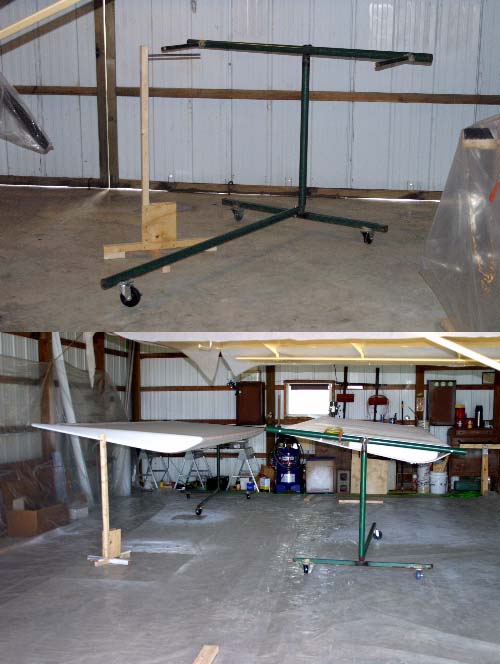
Wing Stands For Painting
This Page Still Under Construction


In deciding what to do concerning how I would paint the wings, I came up with a rather simple design for a stand which would support the wings in a horizontal, flat manner and could be rotated to bring either the top or bottom of the wing to face upward. In my build, I will be adding wing tip strobe lights, which allowed for drilling a 5/8" hole in the fiberglass wing tip edge for the wiring and 1/2" steel tube in the wing tip stand to pass through and support. The hole will be totally covered by the strobe base plate. This will be explained below.

I apologize for the condition of several of the photos as they were taken of the main wing stand "after" I had completed the wings. As such, the wing stands look terrible as they are covered with paint overspray.


Wing Tip Stand

Click to Enlarge
         

Each wing tip stand consists of 1 ea. 2"x2"x45" (Upright), 2 ea. 2"x2"x26-1/2" (Cross Leg Base), 2 ea. 2"x2"x5" (Cross Leg Base Supports), 2 ea. 8"x10"x1/4" plywood support braces and 1 ea. 1/2"x18" "Steel Pipe".

First make the 2"x2" cross legs for the bottom by just screwing 2 ea. 3" wood screws in the center of the cross legs to form an "X". Then screw the 5" 2"x2" feet supports to the upper 2"x2" cross leg so the 2"x2" cross legs will not teeter when set on the floor. Now, take the upright 2"x2", stand it straight up on the cross legs and place the 1/4" plywood braces, 1 ea. on both sides of the upright 2"x2" and screw it into place with 1" wood screws to the top 2"x2" cross brace and the upright 2"x2" to secure and make it steady.

         
Click to Enlarge


CAUTION: As the fiberglass wing tip is "so thin", it would be advisable to strengthen the 45 degree angle portion of the wing at the hole by adding a small wooden stick, like a popsicle stick, inside the wing tip, just below the 5/8" drilled hole and lavishly apply a two part epoxy to strengthen the support the wing tip. It is possible that the 1/2" steel pipe will tear through the side of the wing tip due to the weight of the wing on such a small 5/8" area.


Click to Enlarge
         

Now, drill a 1/2" hole in the top of the 2"x2" upright at 2-1/4" from the top. Using a standard hammer, drive the 1/2"x14" steel pipe into the hole from the plywood side of the brace until the pipe is flush with the back of the 2"x2" upright. The wing tip stand is now finished.

NOTE: The 1/2" steel pipe or tube was used to run the strobe wire through so the wire would not be lost inside the wing, making it difficult to retrieve later.

         
Click to Enlarge


Inboard Wing Stand Fabrication

The 2" green steel pipe was salvaged from an old children's swing set for the main supports of the swivel inboard wing stand. Also 2 ea., 3/4" steel water pipe per stand was used for the arms to be inserted into the inboard end of the wing spars. The "only" items I actually bought was the 4 ea. stationary wheels and 2 ea. swivel wheels for the two stands.


Tools Needed

Use a gas welding torch to both cut and weld the joints and a surface grinder to clean weld areas before and after welding. A drill press would be handy, but a hand drill can drill the bolt and cotter pin holes needed. My brother and I crafted the stand in about three (3) hours.


Click to Enlarge
         

The square top section with slip pipe sleeves was used for the top of the bottom "T" base design and measures 48" long. As the slip sleeves were at a larger angle, the welding torch was needed to remove a "V" section from the inside bend of the elbow to allow bending it into a 90 degree shape. This was done by heating the elbow spine to cherry red, then bending it inward to close the removed "V" section. It was then welded to close and strengthen the seam.

         
Click to Enlarge


Click to Enlarge
         

The upright arm was made by welding a 2-1/2" long collar onto one end, which was cut from another pipe at 38" long. When welding the collar onto the end of the upright pipe, the heat caused the collar diameter to shrink, so it had to be split at the top and another piece of pipe welded to the top of the collar. This was done with the slip sleeve placed "inside" the collar to allow for a more exact fit for the pivot arm.

         
Click to Enlarge


Click to Enlarge
         

Now, the pivot arm needed to be made. First, 1/2" holes were drilled through the ends of the 68" pivot arms at exactly the width from the center of the front spar to the center of the rear spar. Using a 4-1/2" slip sleeve we made from the end of the smaller diameter pipe, we welded it to the center of the pivot arm.

         
Click to Enlarge

We then welded a 1/2" bolt "nut" inside one end of the 3/4" steel water pipe so the bolt could be placed through the arm ends and hold the 3/4" pipe in place while it was welded to the pivot arm. This was done at both ends of both pivot arms.


Click to Enlarge
         

Now for the very last bit of welding. The straight fixed caster wheels were welded to the "T" bottom brace at each end. The swivel caster wheel was welded to the 71" "T" arm end to allow angled movement of the stands.

         
Click to Enlarge


Assembly

Click to Enlarge
         

After drilling a 9/16" hole in the inside end of the "T" support arm and slip sleeve. Insert a 1/2" bolt, then lock washer and nut to secure the bottom "T" section of the stand together.

Now, slide the upright stand post onto the bottom "T" slip sleeve.

         
Click to Enlarge


For the pivot arm slip sleeve, drill a 1/8" hole about 1/4" from the outside lip, all the way through both sides. This will be used for a large retaining cotter pin. A ring was cut from a scrap sheet of rubber/plastic using two size hole cutters, 2" and 2-1/4".

Now insert the slip sleeve of the pivot arm into the collar. Place the rubber/plastic ring onto the sleeve, then insert the cotter pin into the 1/8" hole.

         
Click to Enlarge

NOTE" There is a second cotter pin set into the collar. Drill a 1/8" hole through the collar as shown and through the slip sleeve. Rotate the arm 180 degrees and drill a second 1/8" hole through the slip sleeve. These holes will be used when holding the wing in a flat, horizontal position, either top or bottom, depending on which side you have rotated upward.


Click to Enlarge
         

That's it, you're done!