You will need to do some fabrication to complete the Flaperon actuation parts
and their installation. It will be our endeavor to help walk you through this process.
Flaperon Control Location
Food For Thought
The factory instructions state to place the Flaperon Control in a location which is directly over your head, making you reach up and a little back to adjust your flaperon setting. Why not further forward on the Root Tube? Installation is on right side of root tube.
One suggestion would be for the builder to put a Rony bracket in place up front to make sure the triangle plate won't interfere with it. Also, if the door option is being installed, it's important to install the top door frame prior to installing the flaperon crank so the door frame won't interfere with it either. The flaperon crank can be placed in virtually any location, but the door frame has to be installed in a specific location. After the door frame is in place, locating the flaperon crank is easier and will avoid a conflict. (See Photo) |
|

Click to Enlarge |
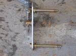
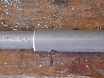
The 1/4" holes would be located as follows: With a felt tip marker, draw two vertical lines from the top of the root tube to the bottom, at a 90 degree angle, 2-1/2" apart. Check that your own triangle plate has the holes along either 90 degree side spaced at 2-1/2". Those are the holes we need to match as they will be on those lines. Drill a 1/4" hole near the top of the rear line, as close to the top of the root tube as possible, without hitting the actual upper surface of the root tube interior.
Since the root tube material is 1/8" thick, I suggest measuring down 3/8" from the top to establish the center for the 1/4" hole. That will allow a 1/8" gap between the bolt and the inner root tube surface. Now, drill the 1/4" hole. Using a carpenter's square, draw another vertical line on the other side of the root tube that matches the placing of the line on the first side. Measure down 3/8" again and drill another 1/4" hole. That will line up the bolt holes better than just trying to drill straight through the root tube in one shot.
Next, drill a 1/4" hole on the front line, 3/8" up from the bottom of the root tube. Copy that line and drill the hole on the other side. Check that it shows the same distance forward of the rear line and drill the 1/4" hole 3/8" up from the bottom of the root tube.
PRO's & CON's Of Doing This
PRO: Two good reasons to move the flaperon control forward. The first is a greater ability of reaching the flaperon crank without feeling for it. If you have arthritis, this would be a far better location. Secondly, there have been several reports that when hitting a rather stiff thermal, the pilots head has actually touched the root tube. Well, if the crank is directly over your head, guess what you are going to hit?
CON: And two good reasons "not" to move the flaperon control forward. In a "Two Place Challenger", this would be a disadvantage "if" you are using your Challenger for instruction as the flaperon crank handle would not be accessable from the rear seat, but would be if placed in the factory recommended location. Also, a forward crank works well with the fiberglass gap cover, but without that cover the crank triangle will be in front of the wing. Any homemade gap cover will have to be modified, since the flaperon pushrod has to run back between the wings.
Flaperon Control Crank Assembly
Factory Location

Click to Enlarge |
|
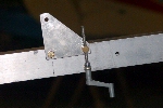
Working from the "right" side of the root tube, the installation of the flaperon control starts with drilling two 1/4" size holes through the root tube as shown in these photos. The upper left hole is drilled, measured from the front edge of the root tube at 10-3/8" for a CH-I and 14-3/8" for a CH-II and the lower bottom hole is drilled at 8" CH-I or 12" CH-II, also from the front edge of the root tube. (Horizontal Mount) |
|
Click to Enlarge |
The upper left hole takes a 1/4" bolt, a nylon washer. Rear of plate takes a nylon washer and 2 or 3 metal washers. On the back side of the root tube, metal washer, castle nut & cotter pin. The crank shaft to bell crank connector or jack screw fitting takes a nylon washer on the front and 2 nylon washers & cotter pin on the rear of the flaperon plate. The eye bolt that holds the crank takes 2 or 3 metal washers on the front and one metal washer & nyloc nut on the rear side of the root tube.
Click to Enlarge |
|
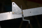
The crank handle is retained with an "AN4-25 bolt with eye to insert the crank handle and retained with a nylon washer and 1/4" nyloc nut in the lower 1/4" hole. The crank handle was formerly supplied with a 1/4" castle nut & cotter pin.
See plate in photo for plate orientation. |
Flaperon Crank Alignment:
Click to Enlarge |
|
When the plate is at 90 degrees to the root tube (with the pivot point and crank located correctly) you should have about 12 threads showing below the actuator. You should have 8 turns clockwise for full up flaperon and still have 3 to 6 threads showing when the mixer plate slot is full forward. You also need enough threads above the actuator to allow for 12 turns of down flaperon, at which point the mixer plate will be full aft. |
|

Click to Enlarge |
NOTE: If you will be installing the door, shoulder harnesses, fiberglass gap seal or large windshield options to your Challenger or moving the location of the flaperon crank assembly, please go to "Root Tube Door Frame Assembly" first before completing this section.
Flaperon Pushrod Assembly

Click to Enlarge |
|
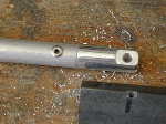
First, locate the 2 pushrod inner sleeves and insert the Threaded Rod End and Clevis Fork into the ends of each pushrod inner sleeve. Drill and secure the ends into the pushrod sleeve with two short 1/8" stainless steel rivet. Each joint of the pushrod connections will require two (2) short stainless steel rivets.
You may need to clean up the ends from aluminum burs for a good fit. |
|
Click to Enlarge |

Click to Enlarge |
|
On the front of the pushrod is a balljoint fitting. To set the balljoint correctly on the threaded end, first, screw the jam nut all the way onto the threaded end. Place the ball joint fitting onto the threaded end and turn it all the way down, then back it off 4 full turns. Now, move the jam nut up against the rear of the ball joint fitting and tighten.
(NOTE: Jam nut not supplied with assembly, but recommended) |
|

Click to Enlarge |
Flaperon, Mixer Plate & Pushrod Adjustments
Starting with the front triangle plate's vertical rear edge positioned at 90 degrees to the root tube, turn the crank handle 8 turns clockwise. This will tilt the triangle plate slightly forward. You should still have 3 to 6 threads showing on the threaded shaft bottom end. |
|

Click to Enlarge |
Note: The rear mixer assembly sometimes comes from the factory bolted down too tight, for shipment purposes. If you can't move it with your hands, you will have to loosen the castle nuts under the root tube. The correct bolt pressure is when you can force the plate forward and aft with strong pressure from your hands alone. If it slides too easily, it's too loose. If you can't slide it at all, it's too tight. Set the correct bolt pressure on that plate before building the pushrods for length.

Click to Enlarge |
|
Go back to the aileron mixer assembly at the rear. Using your hands, push the mixer full forward and put an ink mark on the root tube right at the front of the pointed end on the mixer plate. That marks your full forward plate position, and the crank triangle assembly is at the full forward (8 turns) position as well. Also, establish the rear limit of the mixer plate. Slide it back and mark the root tube with ink next to the rear pointed end of the plate. Then slide it fully forward again, to where it hits the front ink mark. You can begin fitting the pushrod now for correct length. |

Click to Enlarge |
|
Make sure both mixer and flaperon plates are in the forward position. Slip the outer rod over both inner rods. Drill and place clecos into the outer sleeve and balljoint sleeve. Attach the balljoint end to the flaperon plate and the clevis fork end to the mixer plate. Mark the outer tube position on the rear inner tube. Take the entire pushrod off both the front and rear plates. Drill and cleco the rear rod sleeve to the outer sleeve and reattach the rod ends to the plates. |
|
Click to Enlarge |
Your pushrod and mixer plate are in the full forward position. Turn the crank counterclockwise 8 turns and you should see the front triangle plate back in the vertical position. That's neutral. Continue turning counterclockwise until the crank won't go any more. Don't force it, you will be stopped by the rear mixer plate hitting the rear stop in the slot. See if the rear mixer plate is back up against the rear ink mark.
When done this way, you will have about 8 turns forward from neutral and about 12 turns backward from neutral for full mixer travel.
Click to Enlarge |
|
Once all adjustments have been tested and verified, you can now permanently rivet the rear clevis fork rod sleeve to the outer sleeve using 1/8" S/S rivets and reinstall the pushrod. |
|
Click to Enlarge |
SPECIAL NOTE: When installing your pushrod onto the flaperon plate, the jam nut goes on the threaded end of the pushrod, up against the rear of the ball joint fitting. The Nylok nut and large washer goes against the ball itself to hold it against the triangle plate with the smaller washer between the ball and plate. Ball joint fittings are great connectors, the best in fact. When they are new they are nice and snug and secure. As they wear and age they will develop looseness and slop, especially if they are not kept lubricated. At that point it's possible for one to pop apart, where the outside section pops off the ball part. This is why you need the "large washer" on the outside of the ball joint, to trap the outside part of the ball joint so that if it tries to jump off the ball in flight it can't get past the "large area washer". All ball joint fittings on the Challenger are the same. |
|

Click to Enlarge |
That's it, you're done!
Please return to the Featured Build Menu by clicking on your browser's "BACK BUTTON".
|
|


